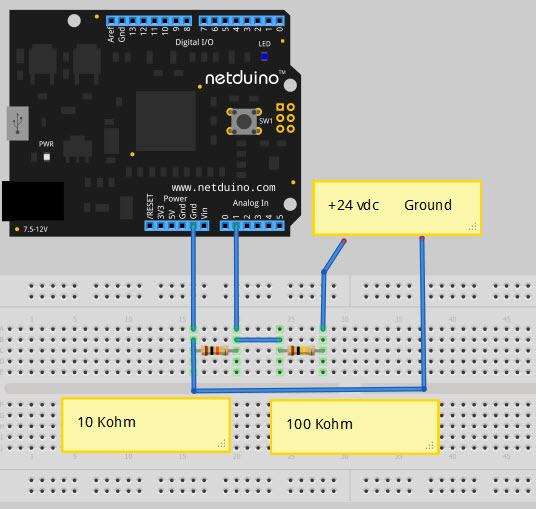
Netduino home hardware projects downloads community

Jump to content


The Netduino forums have been replaced by new forums at community.wildernesslabs.co. This site has been preserved for archival purposes only and the ability to make new accounts or posts has been turned off.

carb's Content

There have been 185 items by carb (Search limited from 28-April 23)


By content type

See this member's


Sort by                Order  

#41982 MG811 CO2 Sensor and Netduino Plus 2

Posted by carb on 20 December 2012 - 10:34 PM in Netduino Plus 2 (and Netduino Plus 1)

ok. I have one of those smd resistor kits This one to be exact. .. It just doesn't have 4.5k in it. What formula do i use for those resistors?

Vout = Vin x (1+R4/R1)

R4 = ((3.3/0.6)-1)x R1

Or like above you can take a 5kohm multi turn pot (the ones that I use are made to go in a printed circuit board and have a multi turn screw to adjust) and set the wiper to 3.3 kohm an the value should stay where you put it and use can adjust the output if needed.

Attached Thumbnails

  • 12-20-12 17-15-13.jpg


#41977 MG811 CO2 Sensor and Netduino Plus 2

Posted by carb on 20 December 2012 - 09:58 PM in Netduino Plus 2 (and Netduino Plus 1)

I've actually done this before.. it wasn't too bad. Would I be able to use a slightly smaller or larger value resister there.. I just looked at the price of those and id have to buy 100 of them at 3 something each just to get 1. I have This booklet of smds on hand and it has a 4.3kOhm and a 4.7kOhm in it. Would one of those work?

Joshua,

Where are you located (country), You should be able to find someone to to sell you a couple of them.

Also check Amazon Resistor Kit or Ebay Resistor Kit.

As to the value I use the formula in the data sheet, You can change the value but may need to change R1 & R4 the value I gave you was keeping R1 the same. Just play with the values using the formula to find a pair that works for you.

You could use a Potentiometer and put 5 vdc on it and adjust the wiper to 3.3 vdc. I have done that with 10 turn pots before.

Chuck


#41971 MG811 CO2 Sensor and Netduino Plus 2

Posted by carb on 20 December 2012 - 08:13 PM in Netduino Plus 2 (and Netduino Plus 1)

Thanks Chuck. could I replace it with one of these?

I'm a developer, not an electrical engineer, so I'm new to this.. however i do have a reqork station at my dispose. Is the smd above the correct package size?

I am not sure I would need to see one of the boards to tell, the removal of the old resistor could be a little tricky. Someone like Arron (often in Chat room) may be able to provide some suggestions. The 805 resistor size is 2.0 mm × 1.25 mm


#41965 MG811 CO2 Sensor and Netduino Plus 2

Posted by carb on 20 December 2012 - 07:09 PM in Netduino Plus 2 (and Netduino Plus 1)

Hi, I just ported over some code for a CO2 Sensor found here and haven't been able to test it yet, but wanted to show everyone on here and see if anyone sees any problems with it. I'm not sure how this will work as it looks like the analog output voltage is 0-5.. If anyone has any suggestions, please let me know.


Joshua,

I haven't looked to much at the code, but it is good to see someone porting the Arduino Code over to C# and sharing it.

As for the 5vdc output that is too high for the Netduino ADC (max. 3.3vdc), but there are a couple of options.

  • Seeing the module output is coming from an Op Amp you can setup a simple voltage divider (1.6kOhm & 3.3kOhm in series)
  • It look like the Op Amp resistor R4 (7.5kOhm) is a surface mount device, you may be able to remove and replace with a 4.5kOhm resistor so that you get 3.3vdc at 10000 ppm CO2.

Chuck


#41954 AnalogInput and Netduino Plus 2

Posted by carb on 20 December 2012 - 04:20 PM in Visual Studio

On the plus 2 it is: (AnalogChannels not AnalogChannel)
int maxAdcValue = 1023; // ADC is 10-bit Resolution

Dave,
On the NP2 it has a 12 bit ADC, ie. 4095 instead for the ReadRaw.


#41927 Shield Base Firmware (beta 4)

Posted by carb on 20 December 2012 - 10:59 AM in Netduino Go

Has anyone experienced, that their analog readings are wrong?

Measured directly on the sensor, i get a value of 0.47v but Shieldbase reads 0.14v... it seems to be dividing the actual value with the voltage...

Nicky which method are you using .Read or .ReadRaw? The .Read gives you a float value 0 to 1.0 the .ReadRaw gives you an integer that reads 0 to 4095.

Chuck


#41463 Network Question

Posted by carb on 13 December 2012 - 08:32 AM in Netduino Plus 2 (and Netduino Plus 1)

Hey Everyone,

I'm new to the microcontroller world and just got my Netduino Plus 2 today. Is there any way to set a hostname for the board so that I can still connect to it over the network without specifically knowing its IP address?

Second newbie question - If I want to use a WiFi shield like the WiFly, I understand it needs the WiFly class libraries/drivers (not sure what the official term is) in order for it to work. Where do I get them?

Thanks.

Mav29x,
Welcome to the forum.

I think what you are asking in question 1 is how do you connect to the Netduino Plus 2 from the internet. To do this (without having a static IP address) you will need a Dynamic Naming Service (DNS). There are some that are free and some that charge. A free one is No-IP.org, a pay one that I use is DYNDNS.

The DNS has the Host Name that you pick, then either the router or the computer runs an update routine that looks for an out of date IP, if it finds the IP is no longer good it contacts the DNS and gets a new one. The DNS keeps track of this. If someone goes to log into your host name it routes it to the new IP address, then your router send it to the Netduino, normally using port forwarding.

So to connect to the Netduino you enter something like "YourHostName.com:1035"

The second question, one of the forum members, Stefan has written a lot of good code called NET Micro Framework Toolbox (the link is in Nicky's post), he has the code in both Visual Basic and C# along with samples to show how it works.

Also you search the forum for WiFly and find information on using it.

Chuck


#41286 Control Large Led matrix

Posted by carb on 09 December 2012 - 10:25 PM in General Discussion

Hi,

Thank you for this information.
Could you please send me any reference on how to construct the circuit or circuit diagram for netduino plus to control the 10X50 matrix.
Please give complete instructions or details of the shift register or any components used in the circuit.
I have the data for each led whether to be turned on or off in a byte array in code.
based on this data the led should glow.

Thanks in advance.

Srinivas

Govind,

Welcome to the forum.

There are a lot of people on the forum that will try to help you, but I would suggest the following:

  • Almost all help here on the forum is volunteered.
  • Most of what you are looking for is already posted on the forum or in the Wiki pages of this forum.
  • Please search and get what information you can find first, then ask specific questions on what you can't figure out.
  • You google to help find code samples and data sheets of parts you think may work and attach to you requests for help (keeps other from having to repeat searches).
  • Look in some of the toolboxes and blogs of the forum members.

When you get a good idea of what you really want to do provide as much information as you can. That way you will get the answers that you need.

Please be patient when waiting, give at least a full day before trying to repeat the question. Remember our members live literly all over the world and it may 5:00 in the afternoon for you but it is 3:00 in the morning for them.

Good Luck with the project.
Chuck


#41245 Connecting an analog joystick to a netduino

Posted by carb on 08 December 2012 - 10:08 PM in Project Showcase

Hello Fabien,
I know this is an old post but I just stumbled upon it. I've downloaded your source for the Analog Joystick test but I'm kind of a newb when it comes to C#. What I dont understand is how to use the class, is it possable that you could give me a small example of how to use AnalogInput Xinput and AnalogInput Yinput in a project?


In case Fabien doesn't see this you can look at a sample that he wrote on CodePlex.com for joysticks. Analog Joystick Sample

Chuck


#41235 NeonMika.Webserver

Posted by carb on 08 December 2012 - 06:12 PM in Project Showcase

I am working on loading this on my N2+.

namespace NeonMika.Webserver
{
    /// <summary>
    /// Interface between NeonMika.Webserver and the executing programm
    /// Use this class to work with your pins
    /// </summary>
    static public class PinManagement
    {
        //Standard output ports
        static private OutputPort Digital0 = new OutputPort(SecretLabs.NETMF.Hardware.NetduinoPlus.Pins.GPIO_PIN_D0, false);

Mercer,

I think part if not all of the problem may be the use of "SecretLabs.NETMF.Hardware.NetduinoPlus". Under 4.2.1 you should use "SecretLabs.NETMF.Hardware.Netduino" it now handles several of the boards.

Chuck


#41186 New to this : Trouble with AnalogInput with Firmware v4.2.0.1

Posted by carb on 07 December 2012 - 09:21 PM in Netduino 2 (and Netduino 1)


I then did temp = (volts-0.5) *100; And the result looks about right

But how do I get the -0.5 from the TMP-36 datasheet? And why the 100?

I have this problem with all the examples I have found - they give you some device specific magic numbers but I cant work out where they come from!

Also how do these numbers transform into the AnalogInput ScaleFactor and offset parameters?

David


The formula is converting the voltage to degrees Centegrade. The TMP36 starts at -50 degrees, and changes .010 volts per degree (10 millivolts). So that when you have 0 volts = -50 degrees, 0.5 volt = 0 degrees and 1.5 volts = 100 degrees. (1000/10=100).

The scalefactor and offset I have not used, I Googled it AnalogInput Class and it appears to allow you to add an offset and a scale factor (could use for calibration) to the ReadRaw method. That is kinda pushing the limits of what I know of C#, if you need a better explaination you may want to try the Chat area, someone may be there that can help.

Chuck


#41182 Wifi timeout

Posted by carb on 07 December 2012 - 08:44 PM in Netduino Plus 2 (and Netduino Plus 1)

Donovan,

Have you looked at Arron's Power Management Class. Power Management

It allows you to cycle the 3.3 & 5.0vdc headers (and other things). This would allow you to remove power temporarily from the shield to reset it, as needed.

Chuck


#41172 New to this : Trouble with AnalogInput with Firmware v4.2.0.1

Posted by carb on 07 December 2012 - 07:29 PM in Netduino 2 (and Netduino 1)

I am trying to use a TMP36 sensor - can anyone help me with the settings I should use for the AnalogInPut scaleFactor and Offset parameters? And what values (and units) the Read and ReadRaw methods return for the correct settings (of those parameters).

Thank-you - I find the lack of any semantic explanations of this new Class a little frustrating!!!

V64,

Welcome to the forum.

The Read is the easiest to use, it gives you an output of 0.0 to 1.0 that you multiply times 3.3vdc.

The ReadRaw varies depending on the board, ie. the Netduino Go & Plus 2 have 12 bit ADC and read 0 to 4095. The other Netduinos are 10 bit and read 0 to 1023.

As far as the TMP36 this post may help Shieldbase and TMP-36

Also you can search the forum for TMP-36, there are a lot of examples.

Chuck


#41068 Need 12v monitoring

Posted by carb on 06 December 2012 - 01:26 AM in General Discussion

Thanks Ckuck.

I'm not sure it is 12 or 24 volt. I'll check with multimeter.

Also; how can i simulate the pressing the button?

You read the voltage between the 2 resistors and ground (make sure that you are across the 10K ohm resistor or the low value of the voltage divider, across 1 resistor is 21.6 vdc the other 2.4 vdc). I reccommend reading the voltage with a voltmeter before connecting the Netduino so as not to apply more than 3.3 vdc.

If you use a digital input when the io is false or for an analog when it reads 0 or < 0.05.

Chuck


#41059 Difference in using VB vs C#

Posted by carb on 05 December 2012 - 11:19 PM in Netduino Go

Chris, Here is the zip file. Hopefully it is not to much, but I zip the project directory. Thanks, Chuck

Attached Files


#41046 Need 12v monitoring

Posted by carb on 05 December 2012 - 08:05 PM in General Discussion

Kaya,

Welcome to the forum.

A simple voltage divider should work, see the attached post Watching Voltage through Analog
If you only need to see if the LED is On or Off you can use either a Analog or Digital input. You will want to drop the voltage down to < 3.3 vdc.

By the way the heading says 12 volt but the text says 24 volt. If it is 12 vdc you can change the ratio of the resistors.

Chuck

Attached Thumbnails

  • 12-05-12 15-27-06.jpg


#40980 Go Socket Breakout

Posted by carb on 04 December 2012 - 10:01 PM in Netduino Go

Are these GHI breakout sockets suitable for use with the Netduino GO?

http://www.ghielectr...log/product/405

Baxter

Baxter,

I have not used the GHI breakout, so I can not say. But I can recommend the modules that Matt designed.

Komodex Labs - GoBus Breakout Module

They cost a little more but give you a lot more options and abilities for testing / programming.

Chuck


#40977 Netduino driven Christmas tree

Posted by carb on 04 December 2012 - 09:29 PM in Project Showcase

Stefan, I am voting for you as head Elf. Merry Christmas.


#40911 Netduino Plus 2 and Adafruit RGB LCD Shield

Posted by carb on 04 December 2012 - 01:58 AM in Netduino Plus 2 (and Netduino Plus 1)

I am currently using Neduino SDK 4.2.1. I have tried to load the toolbox sample for the Adafruit RGB LCD display on both the Netduino Classic and Netduino Plus 2. On the Classic I get an E300000 error code and the wrong mscorlib.dll. I followed the FAQ in wiki could not change the library from 4.1 to 4.2 I then went back to the Netduino Plus 2 with firmware 4.2.1.2 loaded. The shield uses I2C and ties Analog Pins 4 & 5 to the SC & SD connection and has pullup resistors on the I2C lines. With this setup I get errors that it can not find namespace name 'Hd44780Lcd', 'IGPIPort' or 'Mcp23017'. I have added every reference that I can find if no luck. If Stefan (when you get some time) or someone can give me a hint on how to fix this it would be appreciated. Thanks, Chuck


#40901 Building 2 automated vehicles using the WiFly

Posted by carb on 04 December 2012 - 12:54 AM in Netduino Go

Good day everyone,

I've been having this idea for a while but never got a chance to actually work on it but I was wondering if I can make two automated vehicles using the N Go, N+ or N+2 with ultrasound, IR and tons of other sensors but eventually I would like both vehicles talking to each other, so they don't run into each others path, is that possible with the WiFly module reference below?

https://www.sparkfun.../products/10822

This may be helpful when looking at how to control the WiFly module.
NETMF Toolbox for WiFly

Chuck


#40873 Quick question about LCD display on NP1

Posted by carb on 03 December 2012 - 08:41 PM in Netduino Plus 2 (and Netduino Plus 1)

Im using the Adafruit LCD shield kit on my NP1(I2C). I ran the sample code (the one that displays up, down, left, right, and toggles 0 to 1) and it works well as expected. however if i leave it running for approx. 10 hours or more i get random characters on my LCD display scrolling across. Is there a way to lock down my registers to prevent this error, or any other method that will prevent this? Thanks!


I have seen the same problem, Tried to load the program but need to update mscorlib I could not get the sample to deploy under Netduino SDK 4.2.1 with the Netduino Classic. Will try to get it running again when I get a chance.
Chuck


#40728 Netduino Plus 2 ENC28J60 uses SPI1? But where is MISO?

Posted by carb on 01 December 2012 - 10:53 PM in Netduino Plus 2 (and Netduino Plus 1)

Looking at the schematic, I see the ENC28J60 wires marked with the ENC prefix, but I am very confused. It looks like it is SPI1, but ENC_MISO is connected to PB4? Shouldn't it be PA6_SPI1_MISO?

Posted Image

The reason I am asking is because I am adding a profile for NetduinoPlus2 into the new mIP release. Although, I will have to build a firmware with the networking stubbed out or add a disable flag. I suppose I could flash with NetduinoGo firmware... although I suspect the MicroSD won't work with the NGo firmware..?

-Valkyrie-MT

Valkyrie-MT,

Here is the Pinout for the NP2 that Gutworks made, maybe it will help. MISO should be D12, but I am not sure that SPI is fully functional at the moment, I think they have a bug that they are working on.

Chuck

Attached Thumbnails

  • Netduino Plus 2 Pinout.jpg


#40561 Netduino Plus 2 - I2C not working

Posted by carb on 30 November 2012 - 10:23 PM in Netduino Plus 2 (and Netduino Plus 1)

Hi Dave,

thanks!

Here is the code (I'm really sure it isn't the code because it work on the NP+1 and I'm not doing anything fancy and I'm 100% sure I'm reading from the correct register on the device and the address of the device is correct)

using System;
using System.Net;
using System.Net.Sockets;
using System.Threading;
using Microsoft.SPOT;
using Microsoft.SPOT.Hardware;
using SecretLabs.NETMF.Hardware;
using SecretLabs.NETMF.Hardware.NetduinoPlus;

namespace NetduinoPlusApplication_I2C_Example
{
    public class Program
    {
        public static void Main()
        {
            Byte[] _data = new byte[1] { 0 };

            I2CDevice adxl345 = new I2CDevice(new I2CDevice.Configuration(0x53, 100));
            I2CDevice.I2CWriteTransaction write = I2CDevice.CreateWriteTransaction(new Byte[] { 0x00 });
            I2CDevice.I2CReadTransaction read = I2CDevice.CreateReadTransaction(_data);
            I2CDevice.I2CTransaction[] actions = new I2CDevice.I2CTransaction[] { write, read };
            adxl345.Execute(actions, 1000);
            Debug.Print(_data[0].ToString());
        }

    }
}


Egeorgiou,

SecretLabs.NETMF.Hardware.NetduinoPlus needs to be replaced with just SecretLabs.NETMF.Hardware.Netduino. This is a change with the new firmware.

A few quick notes (known issues, temporary workarounds, etc.):

In the meantime, if you are upgrading your Netduino Plus 1 projects to Netduino Plus 2:

  • Remove the SecretLabs.NETMF.Hardware.NetduinoPlus.dll reference from your project.
  • Add the SecretLabs.NETMF.Hardware.Netduino.dll reference to your project
  • Change the deployment target in Project Properties > .NET Micro Framework.

Firmware Update Look at second post.

I tried your code on my NP2, at the first deploy it didn't work but I had no done this step "Change the deployment target in Project Properties > .NET Micro Framework." chnge to .NET Micro Framework 3.0 then back to 4.2 and the program deployed to the NP2. The output is shown in the picture
Chuck

Attached Thumbnails

  • 11-30-12 17-34-09.jpg


#40558 GO! Module - Potentiometer specs

Posted by carb on 30 November 2012 - 10:12 PM in Netduino Go

Thanks for your replies. So that said, if I am planning to use the Potentiometer as an analog potentiometer itself I would have to remove the chip first, right? I am also curious of the resitance of the potentiometer when in full open position. (Sorry no eletronic savvy)

Thanks

Giuliano,

Connecting to just the pot would be difficult and also waste a module why not just buy a potentiometer like the one that likely came with the LCD display (10K ohm) or Radio Shack has some larger ones that you can solder wires onto for a few bucks.

Chuck


#40555 Netduino Plus 2 - I2C not working

Posted by carb on 30 November 2012 - 10:07 PM in Netduino Plus 2 (and Netduino Plus 1)

Hi Chuck,

the image isn't very clear, the lines are not connected together. That wouldn't be clever and I would have picked that up. The same board is moved to the N+1 and it works fine with the originally reference i2c code.

After the post I looked at the picture on a larger screen instead of a tablet and could see it was connected properly. Just didn't want you to smoke the board. :o

Chuck


home    hardware    projects    downloads    community    where to buy    contact Copyright © 2016 Wilderness Labs Inc.  |  Legal   |   CC BY-SA
This webpage is licensed under a Creative Commons Attribution-ShareAlike License.