Let me apologize in advance for what is probably a silly question or mistake on my part. I'm brand new at most of this and I'm a bit lost. I did try to do some searching on this forum in hopes of finding my own answers, but most of the topics are way beyond what I'm working on. I'm literally just trying to build the equivelant of "hello world" type stuff and already stuck.
I just recieved my Netduino and begam working through the Getting Started with NetDuino documentation. I noticed that the Netduino had an old Firmware so I went trhough the steps of flashing it and installing the newer SDKs. I built the first Blinky app with the Netduino and all was well.
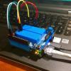
I built the MakerShild and began making the Blinky app work with that (the LED and button). This worked well too.
Once I started trying to write the code to read the (analog) values from the potentiometer on the MakerShield I started getting debugger errors within MS Visual C# Express.
AnalogInput pot = new AnalogInput(Pins.GPIO_PIN_A0);
I get : "Error 1 The best overloaded method match for 'Microsoft.SPOT.Hardware.AnalogInput.AnalogInput(Microsoft.SPOT.Hardware.Cpu.AnalogChannel)' has some invalid arguments C:\Users\Jaime\documents\visual studio 2010\Projects\Blinky\Blinky\Program.cs 18 31 Blinky"
I noticed that there was a mention of "2. New core AnalogInput and PWM classes; backwards-compatible classes available via add-on assemblies". Does this mean that I need to include something more to be able to use the Pins.GPIO_PIN_A0 above?
I hacked around and was able to get the following to compile:
AnalogInput pot = new AnalogInput(AnalogChannels.ANALOG_PIN_A0)
but that doesn't seem to recieve any values from the potentiometer.
The source is attached.
Any tips would be greatly apreciated.
Thanks,
Jaime
Attached Files
-
 Program - Backup.cs 980bytes
12 downloads
Program - Backup.cs 980bytes
12 downloads