

 Find content
 Male
Male


At least I think I am - of mine, not yours, that is :-)
- NeonMika / Markus VV. likes this
|
||||||||||||||
#56684 Netduino & RF transmitter to pair with and control smart electricity socket
One would think you were in control of what devices are accessing your local network?
At least I think I am - of mine, not yours, that is :-)
#56335 My daydream - FPGA/ARM platform
Oh and btw, the thing I wrote about sanding off the chip is no joke, there are vendors doing exactly that!
#56327 My daydream - FPGA/ARM platform
Don't let me tempt and lead you a stray now, keep your eyes on the road and your hands on the wheel there chief!
Ha, ha - I got a special folder on my desktop saying "cool stuff" and a similar one in my email plus tons of little things in anti static bags (many of which are still unopened). I'd say I got gizmos, chips and kits to span a few life times of tinkering but I don't mind, most of the stuff was really cheap and dreaming of what to do with them is free :-)
#56306 Extensive driver for the MCP23S17 I/O expander
You should avoid reading the code :-)
I should probably supply more examples to make things clearer but basically you create input, output and interrupt ports in much in the same way you create any Netduino digital port. Furthermore, you can create buses that are collections of multiple pins that you can use in parallell.
To answer your question in the other thread regarding using the driver along side of other SPI slaves on the same SPI bus - yes, it is possible to share the SPI bus with another slave but you will be facing the same problem that you always do with multiple SPI slave devices on the same bus. You need some software mechanism to change between different SPI configurations in run time between communication with one or the other slave devices.
There have been a number of such very similar "multi SPI" implementations avaialable and I would gladely add support for one. Unfortunately, there's no standard - naturally, everybody who's had the problem have also developed their own solution for it. I think I will make an attempt at adding some kind of generic multi SPI support and will return to that later.
#56202 Networked music player using the mini
Great, that you found it useful!
I saw your antique radio project and I really love the mix of new and old that you get from putting new internals in old machines.
My late mother used to have one similar to yours, you'd have to wait for like 15 minutes for it to get warm before you could use it. Sadly, we didn't keep it.
Cheers!
#56200 Extensive driver for the MCP23S17 I/O expander
What's this?
This thread is about a software driver for a chip called MCP23S17 that provides 16 additional digital IO pins to a micro controller such as the one on your Netduino. 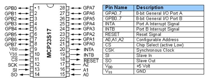 The MCP23S17 gives you 16 digital input, output and interrupt enabled pins over SPI. Up to eight chips can be combined on a single SPI bus to provide a maximum of 128 pins. Background I was originally looking to make a dual ] board (Arduino shield form factor) for this driver to be used with. As so often however, I haven't found the time to complete the board so I decided to release the driver code for others to use. About the software The driver class is actually quite powerful and has a lot of features. The whole interface somewhat mimics that of native Netduino GPIOs in how they are created and used. Full source code is attached to this post. You can create individual pins (input, output, interrupt) and also buses to represent a collection of pins in parallell. The buses are very powerful - for example, you can easily create a 4 pin bus to be used in controlling an LCD or something like that. You can also read and write pins or buses in a so called "burst mode" - this will result in bit streams in either direction at about a tenth of the configured SPI speed. The driver can also be used in a special "direct mode" where all the built-in code for thread safe pin management etc is bypassed in favor of more speed. How to use it Simply download the attached code file and add it to your project and start coding with it - these lines of code the only ones needed for an output port: // create driver to use SPI bus #1 and Netduino pin 17 for chip selectvar chip = new MCP23S17(var io = new MCP23S17(SPI.SPI_module.SPI1, Pins.GPIO_PIN_17);// create a port for pin 1var outport = chip.CreateOutputPort(MCP23S17.Pins.GPIO_1);// drive pin 1 highoutport.Value = true;There are more examples abailable in posts ahead. There's currently no separate documentation for the software but it's easy to adopt and there are lots of intelli-comments in the code to help guide you through. I'd love for you guys to try it out and then hear about your experiences! Hardware Obviously, you need one or more MCP23S17 chips as well. The chip is available in a breadboard friendly DIP28 package and breakout boards are available on eBay and other places. You wire the chip just as you would any other SPI slave device - connect power, ground, miso, mosi, clock, chip select and optionally an additional pin to receive interrupts. NOTE: This driver is for the SPI version of the chip, i.e. MCP23S17 and not the regular MCP23017 which uses I2C. I was planning on isolating the transport layer to support both but I will probably never get around doing that so if you're up for it...feel free! Code revision history: v1.1 - corrected a bug involved in cascading v1.2 - added internal multi SPI mgr V1.3 - made a few insignificant clean ups v1.4 - corrected a nasty bug in the multi SPI mgr  MCP23S17.cs 57.85KB
62 downloads
MCP23S17.cs 57.85KB
62 downloadsAttached Files
#51320 Thinking Of Begining To Use Netduino
I agree, a Netduino is not a good choise for those things and I don't even think the PI could cope. Any of those would probably be a really big detour from achieving what you want.
As all of the bullets are pretty high level stuff, I'd recommend using a PC. Later, you could move to a micro or nano ATX if size is important.
Of course, a Netduino could perhaps handle some of it but what's the point if you got s PC on the side. To be quite honest, I think the stuff you've mentioned taken together could take years to develop no matter what hardware you got.
#51251 Webserver and locking
You should use an interlocked exchange to change the value of the _serverReady varible. The Interlocked.Exchange method will replace the value and return the previous value in a single atomic (unbreakable) operation.
int _serverReady = 1;if(Interlocked.Exchange(ref _serverReady, 0) == 1){ // process request . . . // done, open unlock the door _serverReady = 1;}else{ // server busy}As indicated above, I think you have to declare _serverReady as an integer for this work. You might want to use the volatile modifier on your variable declaration but I don't know if that feally matters in .NETMF.
There might also be a way to configure the listener as synchronous so that the server will never attempt to process requests in parallel. Could be this feature is not available in .NETMF, I'm not sure.
#51199 Proper way to multithread on Netduino
Hi!
There's no special class for "Background threads", they are the same as any System.Threading.Thread. In the post you refer to, the term is used to denote a Thread who's purpose is to process data produced by an interrupt service routine (ISR) in order to avoid lenghty operations in the ISR itself.
The AutoResetEvent is used to have the "background thread" wait for a signal before going to work. It's a good example of the common producer/consumer pattern where the ISR is the producer and the background thread is the consumer.
You can use a System.Connections.Queue object for the ISR to quickly tuck work items away (using the Enqueue method) to be processed by the background thread (using the dequeue method) at a slightly later point in time.
Yes, the background thread would typically run a while loop and perform a WaitOne on the AutoResetEvent as means of syncronization before dequeuing each work item for processing. When there are no items to be processed, the thread goes to sleep and will not wake up again until another work item has been enqueued. If necessary, you can use Thread.Sleep(n) to yield once in while in order not to choke the CPU degrading responsiveness of you application.
Hope this helps!
#50892 Simple sine table
Cool, I've been thinking of that too at some point. It would be really nice to have a PC app where you could draw arb forms in free hand and then upload to the chip/board over USB. Also controlling freq and amplitude from the PC app.
Will the AD9831 retrieve output samples from EEPROM as it goes (like a RAMDAC) or will you be uploading a full "period" to the chip before starting it?
#50876 Compiling and downloading
Hello and welcome to the forum!
You need Visual Studio 2010 or 2012, either the free Express version or any of the commercial ones.
You also need the .NET Micro framework SDK and the Netduino SDK.
Programming, debugging and deployment (firmware upload to the Netduino) is then performed from within Visual Studio by the click of a button. It's all a really simple and straight forward procedure so I guess that's why it is not often discussed explicitly.
Don't worry, you'll be up and running very quickly.
EDIT: You'll find all the required software for download on this page:
http://netduino.com/downloads/
#50813 Simple sine table
[font="arial, sans-serif;"]Below is a simple class implementing a zero-biased sine table with values -255 to 255. I use it frequently and thought I'd share in hope of it being useful to some of you as well. [/font]
Values of the first quadrant ( 0 to pi / 2) are pre-calculated and stored in a byte array. By horizontal and vertical mirroring, values for a full period (2 * pi) is achieved using only a single 256 byte array which should keep memory footprint to a minimum.
[font="arial, sans-serif;"]An integer indexer [/font][font="arial, sans-serif;font-size:14px;"]0 to 1023 (wraps beyond 1023) [/font]is used to get the sine values for angles 0 to 2 * pi.
Hopefully there are none but please let me know should you find any errors.
[font="arial, sans-serif;font-size:14px;"]Note: The [/font][font="arial, sans-serif;font-size:14px;"]microcontroller of [/font][font="arial, sans-serif;font-size:14px;"]Netduino 2 and Netduino Plus 2 features FPU but I don't know if .NET MF takes advantage of that, either way the regular Netduino and Netduino mini does not have an FPU.[/font] // Simple 8 bit sine table public class SineTable { private static byte[] _sin; public static readonly SineTable Sin = new SineTable(0); public static readonly SineTable Cos = new SineTable(256); private int _offset; private SineTable(int offset) { _offset = offset; // 1st quadrant (0...pi/2) in 256 steps if (_sin == null) { _sin = new byte[256]; double a = 0; double da = System.Math.PI / (2.0 * _sin.Length); for (int i = 0; i < _sin.Length; i++, a += da) _sin[i] = (byte)(256 * System.Math.Sin(a)); } } // 1024 = 2 * pi (one period) public int this[int index] { get { index += _offset; index &= 1023; // 1st quadrant? if (index < 0x100) return _sin[index]; // 2nd quadrant? else if (index < 0x200) return _sin[0xff - (index & 0xff)]; // 3rd quadrant? else if (index < 0x300) return -_sin[index & 0xff]; // 4th quadrant else return -_sin[0xff - (index & 0xff)]; } } }You can easily change the resolution by altering the length of the array and the modulo (1023).
[font="arial, sans-serif;font-size:10.5pt;"]UPDATE: The SineTable class now contains two static instances called "Sin" and "Cos" which are used like this:[/font] // some arbitrary angleint alpha = 134; // get sine value for angleint sinval = SineTable.Sin[alpha];// get cosine value for angleint cosval = SineTable.Cos[alpha];
#50754 Seeking economical premade voltage sensor array?
Yes, the general idea was to use an analogue multiplexer that can handle the voltage and then a single voltage divider between that and the Netduino. The CD4067B 16 channel mux/demux can handle up to 20V but Vcc must also be 20V:
http://www.ti.com/li...ink/cd4097b.pdf
If 20V is not readily available you need a step-up converter from 12V which infortunately would increase cost. On the other hand, such converters come quite cheaply on eBay: http://www.ebay.com/...=item1c33d18e42
If you spend some time searching, you might be able to find a demultiplexer that can handle input voltage significantly greater than Vcc and then of course you won't need the converter.
Audi?
#50681 Mocking Inputs?
Instead of Unit-testing, you might consider "black boxing" by writing a corresponding set of interfaces through which data Is introduced. You would then make your fake implementations always returning fixed or random dummy data as needed. Later of course, you would make real (non-fake) implementations.
#50619 Best Hobby Oscilloscope
Hi!
The logic sniffer seems ok for UART and PWM analyzis but not as an oscilloscope:
The analogue bandwidth of 200kHz is way too low and makes it pretty useless
The display is tiny, mine is many times bigger and I still wish it was a lot bigger
Buffers are very small, you can only see small fragments at a time
I think these kind of gadgets are rather cool but don't qualifiy as oscilloscopes. It's like they thought "We got this tiny piece of hardware, let's see if we can make an oscilloscope out of it". It would be better if they'd thought "hey, let's design an oscilloscope and choose whatever hardware meets the requirements".
No, I would put my money on something else.
| ||||||||||||||
|
||||||||||||||
| This webpage is licensed under a Creative Commons Attribution-ShareAlike License. | ||||||||||||||


