Netduino home hardware projects downloads community

Jump to content


The Netduino forums have been replaced by new forums at community.wildernesslabs.co. This site has been preserved for archival purposes only and the ability to make new accounts or posts has been turned off.

hanzibal

Member Since 25 Feb 2011
Offline Last Active Apr 19 2017 07:04 PM
*****

Topics I've Started

Extensive driver for the MCP23S17 I/O expander

19 February 2014 - 10:54 AM

What's this?
This thread is about a software driver for a chip called MCP23S17 that provides 16 additional digital IO pins to a micro controller such as the one on your Netduino.

Posted Image

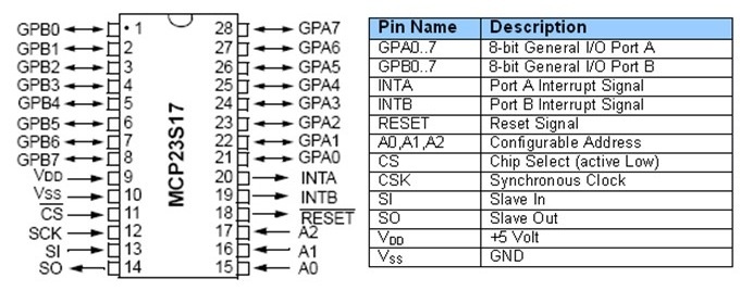
The MCP23S17 gives you 16 digital input, output and interrupt enabled pins over SPI. Up to eight chips can be combined on a single SPI bus to provide a maximum of 128 pins.

Background
I was originally looking to make a dual ] board (Arduino shield form factor) for this driver to be used with. As so often however, I haven't found the time to complete the board so I decided to release the driver code for others to use.

About the software
The driver class is actually quite powerful and has a lot of features. The whole interface somewhat mimics that of native Netduino GPIOs in how they are created and used. Full source code is attached to this post.

You can create individual pins (input, output, interrupt) and also buses to represent a collection of pins in parallell.

The buses are very powerful - for example, you can easily create a 4 pin bus to be used in controlling an LCD or something like that.

You can also read and write pins or buses in a so called "burst mode" - this will result in bit streams in either direction at about a tenth of the configured SPI speed.

The driver can also be used in a special "direct mode" where all the built-in code for thread safe pin management etc is bypassed in favor of more speed.

How to use it
Simply download the attached code file and add it to your project and start coding with it - these lines of code the only ones needed for an output port:
// create driver to use SPI bus #1 and Netduino pin 17 for chip selectvar chip = new MCP23S17(var io = new MCP23S17(SPI.SPI_module.SPI1, Pins.GPIO_PIN_17);// create a port for pin 1var outport = chip.CreateOutputPort(MCP23S17.Pins.GPIO_1);// drive pin 1 highoutport.Value = true;
There are more examples abailable in posts ahead. There's currently no separate documentation for the software but it's easy to adopt and there are lots of intelli-comments in the code to help guide you through.

I'd love for you guys to try it out and then hear about your experiences!

Hardware
Obviously, you need one or more MCP23S17 chips as well. The chip is available in a breadboard friendly DIP28 package and breakout boards are available on eBay and other places.

You wire the chip just as you would any other SPI slave device - connect power, ground, miso, mosi, clock, chip select and optionally an additional pin to receive interrupts.

NOTE: This driver is for the SPI version of the chip, i.e. MCP23S17 and not the regular MCP23017 which uses I2C. I was planning on isolating the transport layer to support both but I will probably never get around doing that so if you're up for it...feel free!

Code revision history:
v1.1 - corrected a bug involved in cascading
v1.2 - added internal multi SPI mgr
V1.3 - made a few insignificant clean ups
v1.4 - corrected a nasty bug in the multi SPI mgr

Attached File  MCP23S17.cs   57.85KB   62 downloads

Exploiting the world of R/C hobby vehicles

03 August 2013 - 07:20 PM

Hi all! During my vacation, I have visited two different archipelagos and by pure impulse, I found my self forced to purchase a radio controlled boat with a brushless electrical motor. The boat really runs and I can only say, I've been away from the R/C hobby field for too long. New battery types and motors make the electric boats run almost as petrol driven without all the fuzz. Anyway, I can think of a dozen cool things and improvements to be done using embedded electronics within the field of R/C boats alone. With respect to you knowledge in emebedded electronics, what have you guys done in terms of improvements and mods within this relatively unexploited area of hobbyism?

Anyone tried XMarine?

26 July 2013 - 10:35 AM

This is not directly related but looks an interesting way to build smartphone apps for interfacing with your Netduino, for example via sockets over a network.


As I understand, XMarine would enable you to use Visual Studio for writing apps for both Android and iOS devices.


http://xamarin.com/


To me it sounds very cool. Has anyone of you guys tried it?


Simple sine table

25 June 2013 - 09:18 PM

[font="arial, sans-serif;"]Below is a simple class implementing a zero-biased sine table with values -255 to 255. I use it frequently and thought I'd share in hope of it being useful to some of you as well. [/font]


Values of the first quadrant ( 0 to pi / 2) are pre-calculated and stored in a byte array. By horizontal and vertical mirroring, values for a full period (2 * pi) is achieved using only a single 256 byte array which should keep memory footprint to a minimum.


[font="arial, sans-serif;"]An integer indexer [/font][font="arial, sans-serif;font-size:14px;"]0 to 1023 (wraps beyond 1023) [/font]is used to get the sine values for angles 0 to 2 * pi.


Hopefully there are none but please let me know should you find any errors.


[font="arial, sans-serif;font-size:14px;"]Note: The [/font][font="arial, sans-serif;font-size:14px;"]microcontroller of [/font][font="arial, sans-serif;font-size:14px;"]Netduino 2 and Netduino Plus 2 features FPU but I don't know if .NET MF takes advantage of that, either way the regular Netduino and Netduino mini does not have an FPU.[/font]

    // Simple 8 bit sine table    public class SineTable    {        private static byte[] _sin;        public static readonly SineTable Sin = new SineTable(0);        public static readonly SineTable Cos = new SineTable(256);        private int _offset;        private SineTable(int offset)        {            _offset = offset;            // 1st quadrant (0...pi/2) in 256 steps            if (_sin == null)            {                _sin = new byte[256];                double a = 0;                double da = System.Math.PI / (2.0 * _sin.Length);                for (int i = 0; i < _sin.Length; i++, a += da)                    _sin[i] = (byte)(256 * System.Math.Sin(a));            }        }        // 1024 = 2 * pi (one period)        public int this[int index]        {            get            {                index += _offset;                index &= 1023;                // 1st quadrant?                if (index < 0x100)                    return _sin[index];                // 2nd quadrant?                else if (index < 0x200)                    return _sin[0xff - (index & 0xff)];                // 3rd quadrant?                else if (index < 0x300)                    return -_sin[index & 0xff];                // 4th quadrant                else                     return -_sin[0xff - (index & 0xff)];            }        }    }

You can easily change the resolution by altering the length of the array and the modulo (1023).


[font="arial, sans-serif;font-size:10.5pt;"]UPDATE: The SineTable class now contains two static instances called "Sin" and "Cos" which are used like this:[/font]

// some arbitrary angleint alpha = 134; // get sine value for angleint sinval = SineTable.Sin[alpha];// get cosine value for angleint cosval = SineTable.Cos[alpha];

Driver for the MCP41100 digital potentiometer

09 June 2013 - 01:20 PM

Hi all!


The MCP41100 is a programmable digital potentiometer with SPI interface and comes in a breadboard friendly DIP-8 package. You can set it to any value between 0 (zero) and 100 kOhm in 256 steps. You can of course tweak it into doing other ranges by wiring in series or in parallel with other (fixed) resistors.


For another project, I needed to produce a variable voltage between 0 (zero) and 5V so I made a simple driver class for it and thought I'll share it with you. Attached you'll find the driver and demo app. It is written for my beloved mini but works with others too requiring only small modifications.

Attached File  miniMCP41100.zip   4.51KB   7 downloads


You simply use it like this:

var r = new MCP41100(new SPI.Configuration(Pins.GPIO_PIN_17, false, 0, 0, false, true, 10000, SPI.SPI_module.SPI1));// set half resistance (i.e. ~50k)r.Level = 128;// set zero resistancer.Level = 0;// ...or you can use the Resistance property to set ~50k like sor.Resistance = 50000;// set ~100kr.Resistance = 100000;

The demo app assumes the IC has been wired as a voltage divider like in this schematic (Pw = output):

Attached File  mcp41100.PNG   20.48KB   25 downloads

When connected that way, you can use it as an a very slow "arbitrary signal generator" meaning you can pretty much draw any signal over time like I did in this post or a nice sine wave if you prefer that:

Attached File  MCP41100_sine.JPG   36.09KB   24 downloads


I guess you could think of the MCP41100 like a "poor man's DAC" :) but since the mini does not have a DAC, it can actually very useful at times as it's also much simpler than to use PWM.


Enjoy!


EDIT: Note that the MCP41100 is not suited for signal generation in general.


home    hardware    projects    downloads    community    where to buy    contact Copyright © 2016 Wilderness Labs Inc.  |  Legal   |   CC BY-SA
This webpage is licensed under a Creative Commons Attribution-ShareAlike License.