
carb's Content
There have been 185 items by carb (Search limited from 29-April 23)
#35203 Netduino: Good starting point for beginners?
 Posted by
on 14 September 2012 - 11:37 PM
in
General Discussion
Posted by
on 14 September 2012 - 11:37 PM
in
General Discussion
Daniel,
The answer lies with your girlfriends interests, if she enjoys puzzles, building thing and being creative then she most likely will enjoy using a Netduino. If she get discouraged easy when it doesn't work on the first try maybe not.
I don't know of anyone that has ever tried to build something and had it work exactly the way they wanted it too or after finishing didn't come up with something else to improve on their first effort. But for most that is the challenge.
Best bet is to get her one to try, she she doesn't like it, then you have one for yourself (you have to look for the silver linings sometimes).
#35206 Sparkfun PIR motion sensor
Posted by
on 14 September 2012 - 11:51 PM
in
Project Showcase
That's what I did. I unplugged the sensor and I read no power at all, well .0L which I think means open or infinite.
Giuliano,
Most multi meters that I have use 0L would mean overload or over ranged, does your meter have auto scaling? If not check that the meter is not in a milli volt range.
Most meters would indicate a voltage (in milli volt range) when not connected just from RF radiation.
Check your meter against a none source such as a AA battery, make sure you use a DC scale not AC. It should read about 1.5 vdc.
As far as the netduino you can hook a wire from the 3.3 volt header to the input pin that would be connected to the alarm. Then move the wire from the 3.3 volt header to ground. If program senses the change the netduino should be good.
Good luck,
Chuck
#35207 MUX Shield
Posted by
on 15 September 2012 - 12:12 AM
in
Netduino Plus 2 (and Netduino Plus 1)
Galibore,
I have not tried that multilexor, but I did buy and put together one that was made by a forum member to work with the Netduino and he has code also. 32 IO multiplexor
I think that I paid $20 for it and it came with the chips and hardware. It works with Stefan's NetMFToolbox which is another plus.
I checked that it worked but haven't got around to playing with it futher.
Chuck
#35209 Netduino Plus Firmware v4.2.0
Posted by
on 15 September 2012 - 12:26 AM
in
Netduino Plus 2 (and Netduino Plus 1)
Arbiter,
One possible source that you may have over looked is old cell phones. I was looking for a 2gb micro when I realized a had a couple of old cell phones that had SD cards still in them (AT&T Samsung dumb phone). If you don't have any old phone some phone stores recycle the old phones and may give you a SD card.
Chuck
#35432 Pan/Tilt Mobile Platform
Posted by
on 17 September 2012 - 08:56 PM
in
Netduino Plus 2 (and Netduino Plus 1)
Adam,
Not trying to down play the many capabilities of the Netduino line, but you would be hard pressed to match the capabilities of a commercial Pan, tilt, zoom (PTZ) camera. They start at around $75.00.
I have an Edimax with 2 megapixil camera, IR for zero ambient light. It can send email, record to SD card, be operated from iPhone or android phone.
I of the better features that would be difficult with memory capacity of a Netdunio is security login and Https: protocols.
Now if you want to be a robot or one of many other projects then Netduino's are great.
Chuck
#35660 5volt question
Posted by
on 20 September 2012 - 09:30 PM
in
Netduino 2 (and Netduino 1)
Perkunas,
There are several current limits that you need to watch. The most limiting is the per pin current rating.
From the Netduino Hardware Specs on Netduino Hardware Page of Netduino.com:
max current: 8 mA per pin
digital pins 2, 3, 7: 16 mA per pin
analog pins 0-3: 2 mA per pin
microcontroller max current: 200 mA total
The current draw for the optical isolators will exceed the pin limits unless you use a transistor between the optical isolator and the IO pin.
The limit for the onboard regulators is 800 milli-amps, but I personnaly don't like to exceed about 50% of that unless I have good heat sinks or fan to help maintain the temperature of the regulators. Also picking a power source that has a voltage that is close to the 5 vdc output helps (7.5 to 9 vdc) the heat produced by dropping the extra voltage is less the closer you are between the input and outputs (heat or power loss = current x voltage drop regulator for Liner Voltage Regulators).
If you want more information on the onboard voltage regulators, go to the hardware page for the Netduino, open the schematic drawing, lookup the part number for the 5 vdc regulator (or 3.3) and google it (MC33269DT-5.0G or MC33269DT-3.3G), you should be able to find a data sheet.
I agree with Dave and reccommend a separate power supply to drive the relays, either mechanical or solid state.
Hope this helps,
Chuck
#35663 LCD for N+
Posted by
on 20 September 2012 - 09:38 PM
in
Netduino Plus 2 (and Netduino Plus 1)
Thanks for the info, I am ordering the 498. Yes, the class would be helpful, I apreciate that.
Giuliano,
You adding a display to the sprinkler system?
I have the 498 and it works very well with Stefan's NetMF Toolbox, it took about 30 minutes to solder all of the pins and headers but you should not have any problems (.1" between connections). Plus you only use a few IOs.
Chuck
#35739 timer question
Posted by
on 22 September 2012 - 12:33 AM
in
Netduino 2 (and Netduino 1)
Perkunas,This is a little hard to explain so here go's
I have light on for 16 hours off for 8 forever loop
simple
I have another loop that kills the 1st one in 14 days
Is there a way to track the 1st loop
My problem is that when the main loop happens the light may have already been on 0-16 hours no way of knowing.
Would like to start it at the same time it left off.
My thinking is, I probably need an external clock.
I may have miss understood your question, but if I didn't I would would pick a loop with a time of say 1 minute. Then on each loop I would increment a counter.
In visual Basic something like this (most likely not correct, meant only to get you started)
dim OnCounter as integer = 0
dim LightOn as boolean = false
OnCounter = OnCounter + 1
LightOn = (OnCounter > 0) and (OnCounter < 961)
if OnCounter > 1440 then
OnCounter = 0
end if
Then use the OnCounter to control a relay for the light.
Also easy to do in C#
Hope this helps.
Chuck
#35740 Early "Getting Started with Netduino Go" software and instructions
Posted by
on 22 September 2012 - 12:42 AM
in
Netduino Go

We are sending your update via USPS, should be there by the end of the year (2013)


Sometimes called snail mail for a good reason.

Chuck
#36028 Verification of Analog Input..
Posted by
on 26 September 2012 - 08:59 PM
in
General Discussion
Hi Coyttl,
What voltage are you looking to measure?
The Analog Digital Converter in the Netduino Plus is a 10 bit ADC. The internal reference is 3.3vdc and the design input to the analog pins is 3.3 vdc also (I don't recommend a applying more than 3.3 vdc). With 10 bit resolution you will get a reading from 0 to 1023 (3.3/1024= 0.0032 per unit).
Most like to take say 20 readings about 20 to 50 milliseconds apart them average then. Repeat this at what ever interval that you want. This reduces errors due to electrical noise etc.
If you want some code that may help you get started there are several examples for TMP36 temperature sensors written in C# and Visual Basic (just replace the TMP36 input with your voltage input.
If you need more help feel free to ask additional questions, the more information you can provide on what you want to do the easier it is for someone to provide the answers that you are looking for.
Hope this helps.
Chuck
#36097 Sparkfun PIR motion sensor
Posted by
on 28 September 2012 - 01:41 AM
in
Project Showcase
Giuliano,After hours of pulling my hair (luckily I have tons of it) can't get the SEN-08630 to work. When measuring with Multi-Meter, there is only 0.1V and no fluctuation at all. I am currently using a 10K Ohms Pull-up resistor. Do you think I am using the wrong Pull-up Resistor, should I use a 47 instead?
This shouldn't be this hard to do. I didn't find any pictures of you setup and unfortunately I don't have one of the PIR sensors, but I can wire it with a switch maybe tommorrow.
A couple of things:
1. I would stick with the 10k ohm resistor, in a previous post you said that you were considering trying a 47 ohm (hope you meant 47k ohm). This resistor limits the current through the sensors and restore a positive voltage (logic level 1) on the input pin.
2. I would use a digital IO for input, they are 5vdc tolerant, plus less coding to make it work, ie. either true or false.
3. On the Sparkfun datasheet it says that the input voltage for the sensor is 12vdc. The Bildr article shows it using 5vdc. But without ordering a sensor I can't try it. If it does need 12vdc then there are several ways of connecting it to the Netduino (do not apply 12vdc to the Netduino).
4. Make sure that you do not expose the sensor directly towards the sun if using outdoors, PIRs don't like that much IR radiation.
Chuck
#36099 Play WAV File
Posted by
on 28 September 2012 - 01:53 AM
in
General Discussion
QuantumPhysGuy,
What kind of wav file are you wanting to play? What type of output / quality are you looking for?
It if fairly easy to send a textfile containing notes to be play on a piezo crystal (code is available on the forum that basicly will get you started). If you want stereo output to speakers you will need hardware to do this. There are several on the forum with postings in this area (Hanzibal for one).
Chuck
#36209 Need Help with DFRduino motor Shield
Posted by
on 28 September 2012 - 10:29 PM
in
Netduino 2 (and Netduino 1)
Kaiser,Hello guys,
I plug a 9V power to the netduino this time and try to run the program again, it didn't work yet.
I noticed there're 4 LEDS near the Motor pin.
when I set MotorDriver.SetState(HBridge.Motors.Motor2, 50); it always red light on, if I gave MotorDriver.SetState(HBridge.Motors.Motor2, -50); the green light on.
However, when I mount the Motor on the pin, there's no more green light, the RED light always ON with some sound and I feel hot from L298P chip. I'm afraid if the chip will explode
Any guys have idea how will it comes? Please HELP!
Without a picture of what you have wired up it is hard to be sure what you actually have.
But in general if a chip is hot you are drawing excessive current or the chip is not heat sinked properly.
The best i could tell you are pulling power from the 5vdc regulator on the Netduino, that regulator has a maximum output of 800 milli amps. That is sufficent for a small 5 volt servo. Anything more should have its own power, normally more than 5 volts depending on the motor. The 2 amp DFRobot shield can handle 5 to 35 vdc on the screw terminals, 6.5 to 12 vdc on the vin connection i.e. barrel connector of the Netduino and uses 5 vdc for logic power from the 5 vdc regulator.
Please take a look at Stefans Wiki page for this DFRobot Motor Shield and the DFRobot Wiki link that is on that page. It explains the difference between PwrIn and Vin and shows how to set the jumpers.
As far as the LEDs by looking at the schematic 2 LEDs are used for each motor, one for forward the other for reverse. If the LED goes out with the motor connected it is likely due to the load dropping the voltage that is needed to lite the LED i.e. you have overloaded the power supply (bad thing
 ).
). Good luck,
Chuck
#36216 Need Help with DFRduino motor Shield
Posted by
on 29 September 2012 - 12:21 AM
in
Netduino 2 (and Netduino 1)
I wouldn't say nothing was wrong and I am not trying to be an A##hole. The condition that you had is called a locked rotor. The current can be over 10 times normal maximum current for the motor, which in turn can burn up a motors windings, commutator, controller or rectifiers of the power supply.Finally, I made it. It turns out that nothing wrong with the wiring and programming. The root cause is my track were too tight and motor cannot be drive properly... I used the twin gearbox and chassis made by Tamiya. When I took off the track, it runs OK!
Next step, I'd like to consider if I need switch to external power maybe give two 9V battery connected in parallel way.
Thank you guys, you do give me a lot of help!
The thing is it sounds like no damage occurred, and we all can learn something out of the trials.
You did a no load test without the motor, a no load test with motor connected but not connected to the tracks would of saved you some time and frustration. I'll need to remember to do that when I start building a robot.
Glad you got it working.
Chuck
#36222 Sparkfun PIR motion sensor
Posted by
on 29 September 2012 - 01:47 AM
in
Project Showcase
Hi Chuck,
No, I didn't get a chance to take a picture of my wiring, also Yes, I was talking about a 47K but didn't get a chance to try it and will stick to the 10K. I am using a digital IO for input. I will try with 12V as suggested and see but first I will try Dave's suggestion to wait at least 1-2 minutes before reading any values and see.
Thank you so much for your input.
Use a voltmeter before connecting to the DIO just to make sure that we don't send to much voltage to it.
Chuck
#36254 The GoBus Upgrade
Posted by
on 29 September 2012 - 12:49 PM
in
Netduino Go
Chris and Elfs,
Great job, Looks like I might have something other than coal under the Christmas tree this year.
Have a great time at the Makers Faire. Then get back to work, please.
Chuck
Chuck
#36273 Netduino Console
Posted by
on 29 September 2012 - 09:29 PM
in
Project Showcase
Bendage,
Very Nice Job, both your project and Mario's should be a great help for those of us with a programming handicap.
I was going to look behind the console, but was afraid that the Phillip Head screwdriver might damage my touch screen.
Thanks again,
Chuck
#36277 Netduino Go Firmware v4.2.0 (Update 1)
Posted by
on 29 September 2012 - 10:57 PM
in
Netduino Go
Chris,
Last night I watched Steve helping a member update his Netduino Go. Most of the problems were associated either with getting the wrong file or missed steps.
I discussed with Steve the need for a procedure to follow (Yes, I work in nuclear power plants and we don't do anything without a procedure).
Today I updated both of my Netduino Go's and ShiedBases and wrote a procedure / checklist that I hope will be a help to others. If you see anything else that should be added please let me know.
I will add the Checklist to Wiki. Checklist PDF Wiki Page
Don't Drink any 32 oz. soft drinks ,
Chuck
Last night I watched Steve helping a member update his Netduino Go. Most of the problems were associated either with getting the wrong file or missed steps.
I discussed with Steve the need for a procedure to follow (Yes, I work in nuclear power plants and we don't do anything without a procedure).
Today I updated both of my Netduino Go's and ShiedBases and wrote a procedure / checklist that I hope will be a help to others. If you see anything else that should be added please let me know.
I will add the Checklist to Wiki. Checklist PDF Wiki Page
Don't Drink any 32 oz. soft drinks
,Chuck
#36311 Toolbox.NETMF question
Posted by
on 30 September 2012 - 07:22 PM
in
Netduino Plus 2 (and Netduino Plus 1)
HI
I have been testing some Socket in NETMF and found Toolbox.NETMF.NET and i have tried the
SimpleSocket, but when i add References to Toolbox.NETMF.Integrated, i cant deploy the project, i got the error please check hardware.
I have comment out all code to se what causing the error and it is when I add reference to the Toolbox.NETMF.NET.Integrated.DLL
it wouldn't deploy any more, if i remove the reference to the Integrated dll it commuincate to the board again.
I have upgraded the Netduino Plus to the latest 4.2 and i use the Toolbox for 4.2
ClrInfo.targetFrameworkVersion: 4.2.0.0
SolutionReleaseInfo.solutionVersion: 4.2.0.0
SolutionReleaseInfo.solutionVendorInfo: Netduino Plus (v4.2.0.1) by Secret Labs LLC
Any one who have a clue or have seen this problem before ?
//
MicroEmb,
The first thing I would try if you haven't yet is to power cycle the board (unplug, wait a couple of seconds and plug it back in).
When you plug it in did the computer recognize the USB connection?
In Visual Studio, select Project, select your program, select .Net Micro Framework. Does it show your board? Change deployment to serial then back to USB, it should show the board.
Try a differrent Micro USB cable.
Have you used the board successfully since the upgrade?
Hope this helps, if not more should be on tonight or tommorrow (Makers Faire in progress in New York today),
Chuck
#36354 Socket.Accept() does not ork
Posted by
on 01 October 2012 - 09:59 AM
in
Netduino Plus 2 (and Netduino Plus 1)
Laurentiss,I have a server that usually works fine.
Except today, I would like to change the Netduino IP Address.
Do you know how to do that ?
The server needs to reply to as simple ping before anything.
Regards
Mfdeploy.exe configuration section allows for setting the a fixed IP address.
Chuck
#36556 Many many PWMs
Posted by
on 05 October 2012 - 01:34 AM
in
General Discussion
Brandon,
I do not know about the Adafruit version but Pololu does have a servo control in both a USB and serial version.
I have a 6 and 18 servo model but so far have only tried with the usb cable. Not from a netduino. Stefan has drivers for the serial only model, but the usb version does take serial inputs also.
Mini Maestro Servo Control
Stefan's drivers are in his .Net Microframework Toolbox.
Chuck
#36574 Servos with Netduino GO
Posted by
on 05 October 2012 - 01:46 PM
in
Netduino Go
Do you have the ground for the Netduino and the negative from the batteries tied togther? You have to have a return from the signal back to the Netduino.I ran into another odd issue last night using a Servo. I have 4 AA batteries which are supplying 6V of power. I hooked them up to my bread board and ran the VCC and GND to my servo, I have the SIG set to PIN D5 on the Netduino Go. When I sent signals to the servo nothing happened. If I wire the VCC and GND directly to the NGO it worked fine.
The servo is rated for 4V - 6V, any idea what would cause this?
Chuck
#36582 Simple wiring question
Posted by
on 05 October 2012 - 03:37 PM
in
Netduino 2 (and Netduino 1)
Perkunas,oh ya guess I wire it like this too
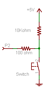
Unless I am missing something you do not need a pullup to make the circuit work.
The following code works fine with a Netduino Classic:
using System;
using System.Threading;
using Microsoft.SPOT;
using Microsoft.SPOT.Hardware;
using SecretLabs.NETMF.Hardware;
using SecretLabs.NETMF.Hardware.Netduino;

namespace NetduinoApplication1
{
  public class Program
  {
    public static void Main()
    {
      InputPort D0input= new InputPort(Pins.GPIO_PIN_D0,false ,Port.ResistorMode.PullUp);
      OutputPort Led = new OutputPort(Pins.ONBOARD_LED, false);
      bool inputstate = false;
      while (true)
      {
        inputstate = D0input.Read();
        Led.Write(inputstate);
        Thread.Sleep(100);
      }
    }
  }
}
The advantages are:
- Less components (no resistors)
- Not applying 5 vdc onto the DIO (they are 5 volt compliant, but normal work at 3.3vdc)
- Uses the resistor.mode.pullup
You can test by placing a jumper wire from ground to D0, which takes it to zero voltage i.e. false. This turns the onboard LED off, remove the wire the internal pullup brings D0 to 3.3vdc i.e. true, onboard LED comes on.
If you want to output to a DIO, change from Onboard_LED to one of the Digital Outputs.
Hope this help,
Chuck
#36601 Simple wiring question
Posted by
on 06 October 2012 - 02:48 AM
in
Netduino 2 (and Netduino 1)
No Problem,Thanks I wasn't sure about those on board resistors or how to use them, so I wired it in as the diagram.
Wired in both the same (1st time wiring the input sides)
Next time Ill use the on board resistors.
Its actually coming from a controller so its a relay that closes and not a switch Principals the same.
IDK as long as it works, thanks for the help.
The relay has contacts the same as a switch.
I actual ran the code on a Netduino Classic 4.2 firmware.
There are a lot of code that you can pull snippets from on the forum, I have been mainly using visual basic, but pulled the code snippet from the project pages "pushing the button, action and reaction" project to make sure I had the correct syntax for C#.
Chuck
#36606 My Simple Go Module wishlist
Posted by
on 06 October 2012 - 04:07 AM
in
Netduino Go
Chris,IO expander modules are a big target for Netduino Go. This is really good input.
For a 16 IO module, would you want terminal connectors or standard 0.1" headers?
5V or 3V3 output? 5V tolerance?
Chris
Both terminal and headers would be nice, I have been thinking about an output board for driving LEDs or relays (mechanical and Solid State) that could sink 100 to 200 ma per output. Just haven't gotten enough time to start it.
Chuck


