Netduino home hardware projects downloads community

Jump to content


The Netduino forums have been replaced by new forums at community.wildernesslabs.co. This site has been preserved for archival purposes only and the ability to make new accounts or posts has been turned off.

klotz's Content

There have been 60 items by klotz (Search limited from 29-April 23)


By content type

See this member's


Sort by                Order  

#419 Why does this happen

Posted by klotz on 14 August 2010 - 01:31 PM in Netduino 2 (and Netduino 1)

When I execute this snippet on the Netduino, it hangs on the xVar.Read(). After that, I can still see Neduino-neduino on in my devices list, but I am not able to access it from the debuger or MFDeploy.exe.
namespace Bug
{
    public class Program
    {
        public static void Main()
        {
            // write your code here
            int xValue = 0;
            int yValue = 0;

            AnalogInput xvar = new AnalogInput(Pins.GPIO_PIN_A0);
            AnalogInput yvar = new AnalogInput(Pins.GPIO_PIN_A1);

            xvar.SetRange(0, 0xffff);
            yvar.SetRange(0, 0xFFFF);

            while (true)
            {
                yValue = yvar.Read();
                xValue = xvar.Read(); //Debugger hangs here and never recovers.
            }


        }

    }
}

So far the only remedial action I have found is to totally erase the Neduino and reflash it.

1. Am I doing something wrong in the code?

2. Is there a safer/better recovery than totally erasing the Netduino?

Help.


#427 Why does this happen

Posted by klotz on 14 August 2010 - 04:23 PM in Netduino 2 (and Netduino 1)

klotz,

Sorry, that's a bug in the Netduino firmware. The AnalogInputs work great--but if you open more than one at a time there's a glitch which causes the Netduino to hang.

You can just erase the program on your Netduino (it takes about 10 seconds). See here:
http://forums.netdui...indpost__p__216

We have an update which fixes the AnalogInput bug scheduled for Monday (in 2 days).

Chris

Thanks for the reference on erase. I had no idea that it could be done that way. The only answer I could find was to totaly erase the board as I described. I will try that next time.

Well that means that at least one of my projects will be on hold til monday.
Is there a list of open items somewhere so I don't have to spend time finding them on my own?
If so, is there also a list of what is going to be fixed and when?
I


#4396 Where to find these connectors?

Posted by klotz on 31 October 2010 - 05:04 PM in General Discussion

Hey,

I'm looking for male PCB mount connectors and their female counterparts (leads). I prefer the connectors have only one way to connect, so you can't switch poles by accident.

I've seen leads like these on LiPo batteries, but I can't seem to find anything useful on RS Online or Mouser when searching for "JST connector".

The PCB connector part looks something like the white connectors on this shield.

I'm EU based so I prefer a supplier like Mouser or RS Online that ships easily to Belgium. Any other EU based shop is good too!

Thanks a lot!

Niels R.

I think this is what you are looking for if the ones in your second picture will work. http://www.sparkfun....roducts_id=8232

Attached Thumbnails

  • Connectors.jpg


#4151 Where can I get an at91sam7x512

Posted by klotz on 23 October 2010 - 08:32 PM in Netduino 2 (and Netduino 1)

As I reported a while back, I killed one of my Netduinos. I recently successfully removed the dead chip, but now I can seem to find any available ( both Mouser and Digikey report out of stock and won't have any 'till after the first of the year). :angry: I believe that I have been able to verify that the board is still viable so I wanted to "glue" a new cpu chip on this guy to test my smd skills. Any one know where I can locate a at91sam7x512?


#760 What is the best programming environment for you?

Posted by klotz on 18 August 2010 - 03:34 PM in General Discussion

What is the best programming environment for you?
Ideas of what to specify:
-Music
-People around you (# of, type of)
-Food/Drinks
-Noise level (cars, people, etc...)
-Computer specs
-anything else


For me:
music - Metal as loud as I can stand it; maybe some dark metal like Cruxshadows, Without Tempation ...
People - Barnie my conure. She counts as a person doesn't she!
Food/Drinks - The days of Twinkies and Orange soda are way behind of me, I have to watch my weight so no food, Coffee or Diet Coke to drink
Noise level - I have no tolerance for that stuff thats why I have the music and over the ears headset.
Computer specs - Two 24" wide screens, one for code, one for design/spec/videos.


#3285 Wait...what's this?

Posted by klotz on 30 September 2010 - 03:13 PM in Netduino Plus 2 (and Netduino Plus 1)

They are apparently all gone. I can't find one anywhere today.


#709 Steps to restore an Erased Netduino

Posted by klotz on 17 August 2010 - 11:41 PM in Netduino 2 (and Netduino 1)

I have read in another thread that you need XP Mode: http://forums.netdui...indpost__p__283

I not sure that you actually need to use XP mode. I am doing all my work in Window7 Ultimate 64-bit native mode.
I didn't have to do anything special to make it work either.


#2783 Stay close to your computer (or come to MakerFaire)...

Posted by klotz on 24 September 2010 - 05:58 PM in General Discussion

Yes, and it's bedtime for sure :)

Chris

I noticed the spec's http://www.netduino....oplus/specs.htm say the microSD holds up to 2Gb. Is this because the Plus uses SPI to talk to the SD card or is it a software limit?


#878 SFE Joystick Shield

Posted by klotz on 20 August 2010 - 12:28 AM in Netduino 2 (and Netduino 1)

Just a quick note for anyone who may want to use the SparkFun Electronics Joystick Shield, DEV-09760 http://www.sparkfun....oducts_id=9760. I bought mine to use for experiments with my Netduino. While it worked fine after I built it, I did find the there were problems with the analog reading for the X and Y pot on the joystick. Following the information I saw here I had added a patch wire from the 3.3 Vdc to Vref. But noticed that the center readings were 66% of full scale. which meant that the min to center would have twice the resolution of the center to max. I am a software engineer not a hardware engineer so it took me a full half hour to realize that the problem was that the pots were biased using 5 Vdc. I change the jumper for Vref to the 5 V source. This did a find job of centering the signal, but the max values were very unstable. I guess I was over driving the A/D. So I cut the trace from 5 V to the joystick and added a wire from 3.3 to the joystick and Vref. Now every thing works just fine. See the attachment.

Attached Thumbnails

  • Joystick board.jpg


#929 SFE Joystick Shield

Posted by klotz on 20 August 2010 - 09:50 PM in Netduino 2 (and Netduino 1)

After the modification to make the Joystick work with the Netduino the next step was to add some extra circuitry to support my next experiment. I wanted to control a servo or two with the joystick I also wanted some indication that the program was in control :D. 
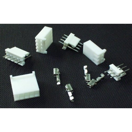
So I added two 3 pin connectors for the servos and a LED. Here is an update to the schematic for the shield just incase someone want to critique it.

Attached Files


#912 SFE Joystick Shield

Posted by klotz on 20 August 2010 - 03:15 PM in Netduino 2 (and Netduino 1)

The biggest reason why AREF is not connected to 3.3V internally is because the SAM7X512 chip doesn't support that natively. The AVR chip on the Arduino has an "internal AREF" as an optional integrated feature.

The other reasons we didn't just wire 3.3V to AREF and skip the AREF pin: [a] we wanted people to be aware that the Netduino was a 3.3V device and to be careful not to put 5V into the analog pins when used in analog mode; [b] we wanted to maintain the chip's capability of having an AREF which varies from 2.7V to 3.3V...for our customers who are using Netduinos for commercial engineering prototypes.

That said, I've chatted with engineering about potentially adding an "internal AREF" option in hardware on a future Netduino board revision. It would be a cool feature to have, for sure. For now, connect the AREF pin header to the 3.3V pin header with a jumper wire when using analog inputs.

Chris

Personally, I like it the way it is. I was not confused by the AREF at all, my problem was that initially I did not pay attention to the fact that the shield had wired the pots to 5 vdc. Then in my haste to compensate I over drove the A/Ds by attaching AREF to 5V. Through this I learned a lot about the Netduino and its relationship to the Arduino. I won't make the same mistake again and hope that my original post will help others.
I conform strongly to the concept of modularity, therefore I feel that if the shield uses A/Ds then it is responsible for supplying the AREF. It may not matter much in the case of a connected shield, but having the A/D source supply the AREF is one sure way of insuring that the A/D's are reading accurately.
So my vote would be, If you are going to add "internal AREF" it should be done via a jumper on the Netduino and the jumper should be left off by default.
I plan to make all my projects supply the AREF for accuracy, so don't break my projects please.


#6865 Question about SPI

Posted by klotz on 03 January 2011 - 12:19 AM in General Discussion

What are the differences between SPI and the other thing that uses TX and RX? I understand that SPI has a clock so the shift register (lets use that as an example) knows when to read the other pin for a HIGH or LOW. but then how does the TX and RX communicate? how does it know when to get the data? Are they both Serial types of communication or not? Any info is appreciated, links are good too. Thanks!


I don't know how much time you have to read stuff, and we could spend a lot of time asking and answering questions so I thought that it may be helpful to supply you with a link to the Wikki page that describes SPI. This may be way more than you wanted to know but there are nuances to using SPI that are not immediately apparent and which many of us take for granted. So here is the Wikki link ( and yes I read it and it is a good description on Jan 2, 2010 :D You know how Wikkipedia can be )
http://en.wikipedia....l_Interface_Bus


#6866 Question about SPI

Posted by klotz on 03 January 2011 - 12:25 AM in General Discussion

What are the differences between SPI and the other thing that uses TX and RX? I understand that SPI has a clock so the shift register (lets use that as an example) knows when to read the other pin for a HIGH or LOW. but then how does the TX and RX communicate? how does it know when to get the data? Are they both Serial types of communication or not? Any info is appreciated, links are good too. Thanks!

Tx and Rx are used for Asynchronous Serial communication which is sometimes described as "self clocking". This is misleading to most users in that the data rate must generally be agreed upon before hand as Chris has stated, the selfclocking come from the method for detecting the begining of the data octet or byte. Here is the Wikkipedia page that describes this http://en.wikipedia....ver/transmitter as before I can only vouch for the correctness as of Jan 2, 2010 when I read it. :D

If I had a choice, I would use SPI over TX/RX because it is easier for me to use. If available and if the distance is not too great I would prefer I2C over SPI.


#6913 Question about SPI

Posted by klotz on 03 January 2011 - 03:28 PM in General Discussion

If available and if the distance is not too great I would prefer I2C over SPI.

Could you break this down a bit more? Distance being what? If I have a central Netduino in the house, and several scattered around the property, what's the prefered for 50 -200 ft, CAT5 cable?


I would not use I2C or SPI for those distances. In the first case, one should not think of I2C or SPI as a protocol for anything say outside the box. Both are intended for communication between ICs or small peripherals, like ethernet chips, lCD displays and the like.
If I have to go more than a couple of feet, then I would start to concider one of the interconnect serial protocols like Async (TTL, RS232, or RS485.)
Then if we are in the range of Room to Room or greater I would concider ethernet.
So in answer to you direct question. At 50-200ft, especially if you have already installed CAT5, go ethernet. The shields for 'duinos are cheap and .NETMF makes it easy to program.


#3239 Power Questions - i.e. Voltage

Posted by klotz on 30 September 2010 - 02:19 AM in General Discussion

You can step the voltage all you want, but it will come as a cost of current. 6V probably would power the Netduino, not 100% on that though, I haven't looked at the schematics yet.

I have run the Netduino, and Parallax boe bot chassis on 4 AA batterys. ( 4 x 1.5 = 6Vdc)
I have been using the same batteries for over a week and had several test runs of the chassis. So I would say, 6VDC will just make it.
Remember you lose about 0.6-1.0 volts to a regulator and the Netduino wants a solid 3.3 Vdc for main power and 5Vdc +- 10% so your can get by.


#320 Newbie Question

Posted by klotz on 12 August 2010 - 09:47 PM in Netduino 2 (and Netduino 1)

I just got my Netduino, what I don't understand is the purpose of the little colorful stamp/piece of paper. Also is there a summary of the netduino sdk anywhere. I am an old guy who is used to having a reference other than the code.


#1061 Netduino servo class

Posted by klotz on 22 August 2010 - 03:26 PM in Netduino 2 (and Netduino 1)

Nice, at least someone got some use out of it! Yeah, this class has been used and tested extensively, so it's all worked out. I will be updating the class in just a sec, too.

I just tried to use the class from the post, and I get an error while compiling "Error 1 The type or namespace name 'Cpu' could not be found (are you missing a using directive or an assembly reference?)"

While I am new to using C# this is not the first class library I have made so I am a little confused about why I am getting the error. I did copy and pasted the file from the post.
Any suggestion?


#1080 Netduino servo class

Posted by klotz on 22 August 2010 - 06:52 PM in Netduino 2 (and Netduino 1)

Did you include the Microsoft.SPOT.Hardware reference? You probably also need SecretLabs.NETMF.Hardware and SecretLabs.NETMF.Hardware.Netduino

So it was a problem with the way I created the project, not the source at all. Once I went to References under the solution explorer and added the Microsoft.SPOT.Hardware, it build just fine.
Like I said I am still a nubie when it comes to C#.

BTW: That and SecretLabs.NETMF.Hardware. Oops. :lol:
Thanks.


#3216 netduino harness

Posted by klotz on 29 September 2010 - 10:21 PM in Netduino 2 (and Netduino 1)

I built my own imediately after getting my 'duino and FEZ domino. I had the box in my scrap box and added the breadboard and a 5volt regulator. I have a chassis plug on the back of the box to connect VIN.

Attached Thumbnails

  • Duino workstation 001_small.jpg


#10802 Keypad driver and scheme

Posted by klotz on 10 March 2011 - 10:18 PM in Netduino 2 (and Netduino 1)

I did a 4x4 keypad decoder as well. In my case I used a 8574 chip and the I2C bus, but the basic idea is the same. You may get some ideas from the code I wrote for that, see http://www.fezzer.co...-port-extender/

Attached Thumbnails

  • I2C_HDI.jpg


#10803 Keypad driver and scheme

Posted by klotz on 10 March 2011 - 10:22 PM in Netduino 2 (and Netduino 1)

And then here is my solution to the Sparkfun keypad
using System;
using System.Collections;
using System.Threading;
using Microsoft.SPOT.Hardware;


namespace Sparkfun_12_key_keypad
{
    public class Keypad
    {
        private InterruptPort Col1;
        private InterruptPort Col2;
        private InterruptPort Col3;
        private OutputPort Row1;
        private OutputPort Row2;
        private OutputPort Row3;
        private OutputPort Row4;
        private uint column1 = 0;
        private uint column2 = 0;
        private uint column3 = 0;
        private uint recieveKey;


        void Col_OnInterrupt(uint whichCol, uint data2, DateTime time)
        {
            recieveKey = 0xFFFFFF;

            for (uint Row = 0; Row < 4; Row++)
            {
                switch (Row)
                {
                    case 0:
                        Row1.Write(false);
                        Row2.Write(true);
                        Row3.Write(true);
                        Row4.Write(true);
                        break;
                    case 1:
                        Row1.Write(true);
                        Row2.Write(false);
                        Row3.Write(true);
                        Row4.Write(true);
                        break;
                    case 2:
                        Row1.Write(true);
                        Row2.Write(true);
                        Row3.Write(false);
                        Row4.Write(true);
                        break;
                    case 3:
                        Row1.Write(true);
                        Row2.Write(true);
                        Row3.Write(true);
                        Row4.Write(false);
                        break;
                }
                if ((whichCol == column1) && (Col1.Read() == false))
                {
                    recieveKey = (Row*3);
                    break;
                }
                else if ((whichCol == column2) && (Col2.Read() == false))
                {
                    recieveKey = (1 + (Row*3));
                    break;
                }
                else if ((whichCol == column3) && (Col3.Read() == false))
                {
                    recieveKey = (2 + (Row * 3));
                    break;
                };
            }
            Row1.Write(false);
            Row2.Write(false);
            Row3.Write(false);
            Row4.Write(false);
        }

        public Keypad( Cpu.Pin Col1, Cpu.Pin Col2, Cpu.Pin Col3, Cpu.Pin Row1, Cpu.Pin Row2, Cpu.Pin Row3, Cpu.Pin Row4)
        {
            this.Col1 = new InterruptPort(Col1, true, Port.ResistorMode.PullUp, Port.InterruptMode.InterruptEdgeLow);
            this.Col2 = new InterruptPort(Col2, true, Port.ResistorMode.PullUp, Port.InterruptMode.InterruptEdgeLow);
            this.Col3 = new InterruptPort(Col3, true, Port.ResistorMode.PullUp, Port.InterruptMode.InterruptEdgeLow);
            this.column1 = (uint)Col1;
            this.column2 = (uint)Col2;
            this.column3 = (uint)Col3;

            this.Row1 = new OutputPort(Row1, false);
            this.Row2 = new OutputPort(Row2, false);
            this.Row3 = new OutputPort(Row3, false);
            this.Row4 = new OutputPort(Row4, false);

            this.Col1.OnInterrupt += new NativeEventHandler(Col_OnInterrupt);
            this.Col2.OnInterrupt += new NativeEventHandler(Col_OnInterrupt);
            this.Col3.OnInterrupt += new NativeEventHandler(Col_OnInterrupt);
        }

    }
}

You just have to make sure that the pins you use for Columns are interrupt pins.


#10829 Keypad driver and scheme

Posted by klotz on 11 March 2011 - 10:46 PM in Netduino 2 (and Netduino 1)

The ammount of current being dumped into the interrupt is not a issue, what you should be worried about is the ammount of current being drawn on the outputport driving the columns. Even in that case, the ammount of current is negligable. Worstcase for any one driver would be 4 keys. If you are seriously worried about it you can mitigate the problem by driving the 4 rows and have the Columns as the interrupts, in that case the worse case would be 3 keys.


#3591 Just cooked my 'duino

Posted by klotz on 07 October 2010 - 12:11 AM in Netduino 2 (and Netduino 1)

I unfortunately plugged my shield in off key without noticing it and when I powered my Netduino it failed to connect. I tried to find the software reason it wouldn't connect rather than what could be wrong with hardware. Once I notice the shield was not plugged in correctly, I disconnected the power removed the shield and allowed the duino to cool. TOO LATED :o Well live and learn. From now on, I won't power-up without checking the connections. Oh well now I have to order a new one Just had to get that off my chest.


#3594 Just cooked my 'duino

Posted by klotz on 07 October 2010 - 12:39 AM in Netduino 2 (and Netduino 1)

I ALWAYS triple check my connections. So far, I have not fried even a single component.

I have gotten quite close though ;) Just ask my temp sensor that had a backwards pinout to the dumb datasheet....


I guess I shouldn't try to work on my board with distractions. Just did not notice the pins that were not in their sockets.


#3596 Just cooked my 'duino

Posted by klotz on 07 October 2010 - 02:15 AM in Netduino 2 (and Netduino 1)

Hi klotz,

No fun at all. It sounds like it got fried, but you may want to try erasing the Netduino (using the ERASE) pad and seeing if you can reprogram it. It's probably fried--but there's a small possibility of recovery...

Chris

P.S. Reverse power protection and a resettable fuse are built into the Netduino. And the odd pin spacing for shields helps keep pins in the right place. But while Netduino is designed to take a certain amount of abuse, it is possible to fry a pin (or in more extreme cases, to fry a whole Netduino). Most users will be fine--but it makes me sad to see one get electrocuted...


He's dead Chris.
No amount of protection can survive an unattentive user. Just got to excited about testing my two ethernet shields and didn't notice I had plugged it in wrong. The Seeeduino shield is wider than most so it is not as easy to see the pins if you don't pick it up and inspect it.
And of course I was convince I had checked it so I let it cook while I trouble shot the failure to connect. The Atmel was way hot, and I can't get any response from it at all except a very bad smell and lots of heat.
(Kind of reminds me of like Washington D.C. or Springfield, IL)
I'll mount this one on the wall with a note "CHECK THE SHIELD" hanging from it.
That's what overconfindence will get you.


home    hardware    projects    downloads    community    where to buy    contact Copyright © 2016 Wilderness Labs Inc.  |  Legal   |   CC BY-SA
This webpage is licensed under a Creative Commons Attribution-ShareAlike License.