I just had another look at your code and I see that you check Available before doing anything at all. Maybe you have changed that now, but I think Available can be zero which just means that no data has been read in advance for you and that you must read it all by yourself - there's still an incoming request to be serviced. If not already done, put a Debug.Print statement immediately after the Accept statement and see what happens.
hanzibal's Content
There have been 386 items by hanzibal (Search limited from 12-July 24)
#49366 Netduino Plus 2 Web Server
 Posted by
on 12 May 2013 - 07:20 PM
in
Netduino Plus 2 (and Netduino Plus 1)
Posted by
on 12 May 2013 - 07:20 PM
in
Netduino Plus 2 (and Netduino Plus 1)
#49377 RC6 Decoder Class
Posted by
on 13 May 2013 - 09:43 AM
in
Project Showcase
Phil, this is great since I'm a big fan of using IR remotes in my Netduino projects.
I've been using this NEC IR-receiver class which works great with many of the cheap credit card sized remotes available on eBay:
http://forums.netdui...col-ir-decoder/
It works well but does not support command repetition (such as volume adjustment).
I'm using it in several projects including my CD-player and I2C-driven LCD.
Hi Phil,
Great Post, I just decoded my Philips television remote control, but now I'll begin my search in how to transmit the data using IR trasmitter!
Anyone got any help on doing this?
Thank you!
You should be able to use SPI to send IR. Have a look at this thread on how to accomplish that:
http://forums.netdui...ased-ir-remote/
In the same thread I also wrote about how IR-transmissions are modulated in general using so called "burst pairs".
#49384 Outputting to I/Os in parallel
Posted by
on 13 May 2013 - 02:10 PM
in
Netduino Plus 2 (and Netduino Plus 1)
Hi!
I have some vague notion of reading somewhere that you could group pins together to form a parallel data bus on the version 2 boards but I can't find that info now and could be that was only a feature of the CPU itself and hasn't been made available to managed code yet. Perhaps someone can correct me on this?
So from what I know, the short answer would be no, I don't think there's any parallel bus.
...but - there are plenty of different solutions involving some external component. For example, with a shift register you can create a virtually parallel bus using SPI to drive it. You might want to look at the 74F166 which is an 8 bit bidirectional shift register:
http://www.nxp.com/d...heet/74F166.pdf
Also there's the PCF8574 8 bit quasi-bidirectional I2C I/O expander which is easy to use. Both of these ICs are available in breadboard friendly DIP16 packages.
For the latter, I've written a driver class and I2C bus manager that can be found in this post
#49396 multi threading problem
Posted by
on 13 May 2013 - 06:57 PM
in
Visual Basic Support
Hi!
Start by removing the do...loop in Sub Main, instead use Thread.Sleep(Timeout.Infinite).
Next, both your threads will exit as soon as sensor and button reads true respectively. Once a thread exits its method, it stops running and won't get called again per se. Therefore, replace the "loop untill..." with just "loop" in each of the corresponding methods and it should work better.
Better still would be for you to declare both sensor and button as Interrupt ports and then use the interrupt to turn motor rotation on and off depending the edge being high or low.
#49399 multi threading problem
Posted by
on 13 May 2013 - 09:48 PM
in
Visual Basic Support
I forgot to say earlier; move the if block to inside the do...loop for both threads.
#49400 Netduino plus 2 + Real time clock + RFID
Posted by
on 13 May 2013 - 10:02 PM
in
Netduino Plus 2 (and Netduino Plus 1)
Hi!
I don't know about the RFID reader but I think the Netduino does not have enough processing power to drve that LCD. Take a look at the Nokia 5110 instead, I know people on the forum have had success with that.
About the RFID, what do you mean by "Real Time Clock RFID Sensor"?
I'm asking since normally, RTC and RFID are not integrated but two different modules.
#49417 Netduino plus 2 + Real time clock + RFID
Posted by
on 14 May 2013 - 10:18 AM
in
Netduino Plus 2 (and Netduino Plus 1)
Cool, seems I was wrong about the LCD - Good!
#49420 Old school ft. New school: Snake with a Lumia 920 controlling a 5110 LCD usin...
Posted by
on 14 May 2013 - 11:42 AM
in
Project Showcase
Very nice, at first I didn't see the Lumia but only an old 5110 but then I noticed the animated "fly by" arrows and reallzed the 5110 was never capable of that.
Thanks for sharing!
Edit: also, congrats on becoming a Nokia Developer Champion!
#49457 Issues with buttons and LCD
Posted by
on 15 May 2013 - 05:20 AM
in
Netduino 2 (and Netduino 1)
I agree, it's hardly a h/w error "anymore". Using a shiftregister would probably help but you need to change your wiring to use SPI with the shift register and probably have to use a different library (e.g. Mario's) too.
Before trying that, I could post you some code to try when I'm home after work today. That code would be more or less a drop in replacement.
#49461 New to this, I want to make sure I use the right tools
Posted by
on 15 May 2013 - 11:12 AM
in
General Discussion
Hi Dave and welcome to the forum,
I totally agree with Dave 
Seems like a good kit to start with. As you know the Netduino Plus 2 has networking capabilities and can send emails and such. As for sound, you can use PWM to play a chime on that piezo buzzer.
Since you're an experienced developer, I'm sure you'll manage to put the door bell/mailer together.
Good luck!
#49475 Issues with buttons and LCD
Posted by
on 16 May 2013 - 12:20 AM
in
Netduino 2 (and Netduino 1)
Sorry about the delay, couldn't find the code so I had to write it all over again 
Anyway, attached is some code you can try. It's a small Hd44780 demo app using bit banging to drive the LCD. I wrote the app for the Mini but you should only need to change the pin assignments and using directives according to your board. It works perfectly on the Mini and hopefully it will on your board too.
Here's a couple of pictures showing what it should look like when running:
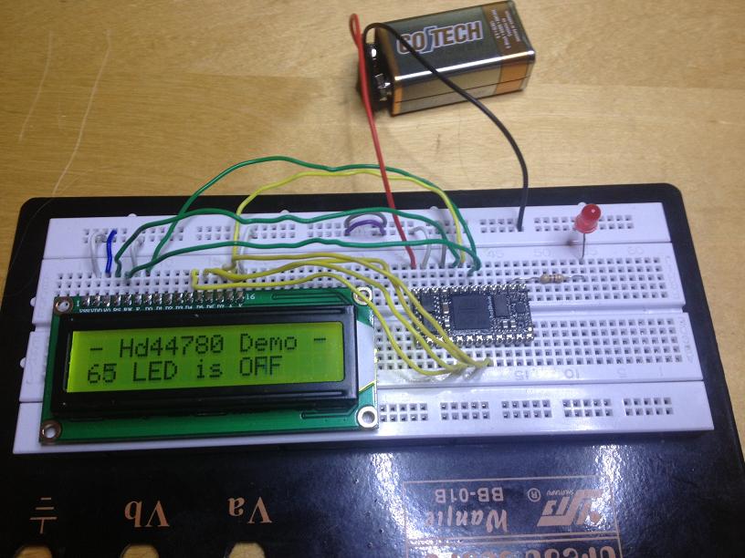
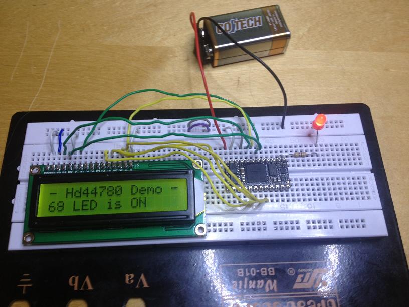
In the pictures the wiring may look funny because I use PWM to control brightness and contrast. That way I don't need any potentiometers and there's a few lines for this that you can uncomment if you want to use PWM. Should you decide to do so, first measure the currents to make sure you can drive the LCD straight off the PWM outputs. In my case the current is only some 4mA so it's fine.
Good luck!
 Hd44780Test.zip 4.55KB
4 downloads
Hd44780Test.zip 4.55KB
4 downloads
#49480 Issues with buttons and LCD
Posted by
on 16 May 2013 - 03:52 AM
in
Netduino 2 (and Netduino 1)
That is strange, the wiring looks ok to me and the corresponding gpio# in code checks out too.
You shouldn't have to tweak anything more than the gpio# so I find it very strange.
1. The code does compile yes?
2. If so, exactly what do you see when you run the app?
3. If you see something (like garbeled text or so), could you perhaps take photo of it?
EDIT: Would it be possible to isolate the board and LCD from everything else, i.e. temporarily disconnect all the other stuff or maybe you have an extra board, a regular N, NP or mini you could try the LCD alone with?
#49484 Netduino Plus 2 Web Server
Posted by
on 16 May 2013 - 06:49 AM
in
Netduino Plus 2 (and Netduino Plus 1)
Sounds like a good decision given the benefits you see in a relay server and the time invested in fruitless attempts to getting it working without one.
Still, its remarkable that it does not work, I have such a hard time believing that requests via a router is treated any different that ones coming from a local network.
Have you actually checked to make sure it has nothing todo with bytesAvaible? That is one thing that could be handeled differently.
I agree, it would be very interesting to hear if others are experiening this issue.
#49485 Outputting to I/Os in parallel
Posted by
on 16 May 2013 - 07:46 AM
in
Netduino Plus 2 (and Netduino Plus 1)
A really cool and useful feature of the PCF8574 8 bit I2C I/O Expander is that it is quasi-bidirectional meaning the pins work in both directions without the need for being configured in one direction or the other.
Also, I'm currently working on a driver class for the MCP23S17 which is a 16 bit I/O Expander with SPI interface. With my software, you can use it pin by pin or group pins together to form one or more parallel buses. This chip is also bidirectional and has excellent per pin interrupt handling. I'll be posting the code when done.
Also, I'm currently working on a driver class for the MCP23S17 which is a 16 bit I/O Expander with SPI interface. With my software, you can use it pin by pin or group pins together to form one or more parallel buses. This chip is also bidirectional and has excellent per pin interrupt handling. I'll be posting the code when done.
#49491 HT12E and HT12D
Posted by
on 16 May 2013 - 11:48 AM
in
Netduino Plus 2 (and Netduino Plus 1)
Hi!
I suppose that would depend on the rate at which data must be processed and how lengthy transmissions are.
I think it's possible to emulate the decoder using a interrupt pin connected to the data out of the RF receiver since interrupts are correctly time stamped and buffered until your app is ready to examine them. However, if the reception is continuous or comes in too lengthy bursts, the interrupt buffer would overflow and cause communication to fail miserably.
It's probably harder to emulate the encoder depending on the modulation and data rate but maybe it could be done using SPI.
Could you perhaps refer to a description (or picture) on how data is modulated outside the RF link?
#49495 DFROBOT Buggy
Posted by
on 16 May 2013 - 04:33 PM
in
Project Showcase
Hi Paul, nice work!
As for me, I've still not really taken the leap over to things that move besides for servos and stepper motors.
My dad recently got himself a robo mower and that came to mind when I saw your buggy. Is that perhaps what you had in mind or is it just for plain old fun?
Maybe you saw my CD player and having 12+ CD/DVD drives on my desk, I'm thinking of maybe making a x/y plotter with the laser sleighs from a couple. Those are actually 4 wire stepper motors in case you didn't know - in fact, a CD drive contains no less than 3 motors of which one is a stepper driving the laser sleigh using a worm screw to move along the guides in a very precise manner.
Anyway, good luck with the buggy!
#49500 DFROBOT Buggy
Posted by
on 16 May 2013 - 08:24 PM
in
Project Showcase
Yes, well it can't be for all the sex and drugs and rock'n roll, that's for sure ;-)
#49505 Issues with buttons and LCD
Posted by
on 17 May 2013 - 06:59 AM
in
Netduino 2 (and Netduino 1)
I know that appearance only too well, I'm now quite positive it's a timing issue. Before employing an alternate board, you can try tweaking the code a bit. If you dive into the driver source, there's a method called _WriteNibble that basically does all data transfers to the LCD. As you will see, there are two lines of code driving the E pin. For starters you could try increasing the delay before lowering the pin to 2ms instead of just 1ms. The delay shouldn't be necessary since minimum data setup time is just 80ns but in comparison to which, even 1ms is an eternity but still worth a try. If that does not help, you can try other means but I'm on a train now and haven't got access to the code.
EDIT: When looking more closely to your setup, I noticed that your pull-downs on d0...d3 are wrong - I meant to pull down each of them separately. At this point, you can simply remove the pull-downs all together.

#49508 Issues with buttons and LCD
Posted by
on 17 May 2013 - 01:43 PM
in
Netduino 2 (and Netduino 1)
Not really, it's just because they're not needed anymore and the fact that you have bridged them which might not be 100% healthy.
I feel very confident it's a timing issue. When thinking about it, the fact that you do see characters suggests that the LCD controller is actually correctly configured for 4 bit 16 x 2 mode and hence responds to commands. So why does data get garbled?
This in turn suggests the problem has to do with the RS pin rather than the E pin....Have a look at fig. 25 on page 58 and then page 52 in the d/s describing the timing characterstics:
https://www.sparkfun...LCD/HD44780.pdf
The driver works on my mini but then again, the NP2 is much faster which could affect timing. Anyway, before going down that lane, I think you should try the E pin code mod I suggest earlier. If that doesn't help, you could try moving the E pin assertion to just before the data pins are written to.
I believe you're almost there now!
#49530 Issues with buttons and LCD
Posted by
on 18 May 2013 - 01:33 PM
in
Netduino 2 (and Netduino 1)
That's great news!
Not to be a kill joy, but the necessity of such a long delay is likely only a symptom of the actual problem likely being something else. l should think it has to do with the RS pin and it should be further investigated. I might look into it when I find the time.
In my PCF8574 based driver, the delay is only 100us and that works perfectly well.
If you decide to make a PCB for your project, may I suggest you use the pcf8574 io expander. It's I2C and should save you some 4 pins of which you could use one for controlling brightness via PWM, periodically sampling a photo resistor to automatically adapt to variations in ambient light (daylight compensation). The code is available in this post:
http://forums.netdui...-and-ir-remote/
#49531 New Netduino on its way? (cryptic homepage)
Posted by
on 18 May 2013 - 02:39 PM
in
General Discussion
Have you seen the start page?
 Looks like something new is coming...
Can any of you decipher the hieroglyphs?
Actually, I had a hunch since Stefan has been very quiet for some time now and statistically*, that is a clear signal!
*) Based on random samples taken from a population of one (1)
Looks like something new is coming...
Can any of you decipher the hieroglyphs?
Actually, I had a hunch since Stefan has been very quiet for some time now and statistically*, that is a clear signal!
*) Based on random samples taken from a population of one (1)
#49537 Mayhew Labs MuxShield and TI 74HC4067
Posted by
on 18 May 2013 - 07:56 PM
in
Project Showcase
Sure, just change the pin names.
Eric, how fast can you cycle through pins with this thing?
#49546 New Netduino on its way? (cryptic homepage)
Posted by
on 19 May 2013 - 03:53 AM
in
General Discussion
I'll second that but suspect otherwise since the majority of users seem to prefer boards like the NP2 On the other hand, I get the feeling that the Go! has not been a big enough sucess to justify going further down that lane but then again, nor seems the Cerb40 from GHI. However, there is now a big gap between the mini and the N2 so I wouldn't be all that surprised if my prayers have been heard after all :-) I'd really love to see a mini on steroids!
#49547 Mayhew Labs MuxShield and TI 74HC4067
Posted by
on 19 May 2013 - 04:05 AM
in
Project Showcase
Basically, you need to set CurrentPin between reads from each different pin.
About the pin names, it could be you don't have to change anything.
#49558 Mayhew Labs MuxShield and TI 74HC4067
Posted by
on 19 May 2013 - 11:19 AM
in
Project Showcase
I don't have an NP2 but those errors suggest Pins.GPIO_PIN_Ax are not const but variables on the NP2 which seems a little odd.
Anyway, try removing the leading "const" in each of the three lines.
The board should not get _hot_ so check your wiring and make sure you're not using more current than the board(s) can handle.


