 Posted by
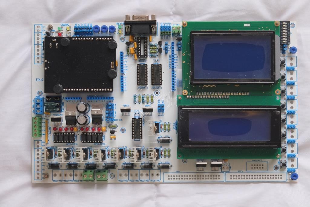
Not sure if this will get picked up cause this post is pretty old. I really need to get some more performance out of a HD44780 I'm using over spi. I'm just using the stefan's .netmftoolbox at the moment to drive it using the 74hc595 class. I thought the perfomance would be ok except that it is not really. I've got the code copied into my project but have to change it because the wiring is different on the custom PCB i have made. can anyone help me modify the code to allow for my different wiring? Bit_shifting is a little out of my depth. All though, come to think of it. I would still need to use the 74ch595 class because the are three 595's in the chain. if I were to go and use the spi directly it would write random stuff to the next 2 chips in the chain. Which brings me to the next question. would using this display driver get me anymore performance. seeing that It would have to write to the spi over the 74hc595 class from the netmftoolbox anyway. Anybody?
//#define CRONO

using System;
using Microsoft.SPOT;
using Microsoft.SPOT.Hardware;
using System.Threading;

using Cet.HW.GDI;

/*
 * Copyright 2012, 2013 by Mario Vernari, Cet Electronics
 * Part of "Cet Open Toolbox" (http://cetdevelop.codeplex.com/)
 *
 * Licensed under the Apache License, Version 2.0 (the "License");
 * you may not use this file except in compliance with the License.
 * You may obtain a copy of the License at
 *
 *     http://www.apache.org/licenses/LICENSE-2.0
 *
 * Unless required by applicable law or agreed to in writing, software
 * distributed under the License is distributed on an "AS IS" BASIS,
 * WITHOUT WARRANTIES OR CONDITIONS OF ANY KIND, either express or implied.
 * See the License for the specific language governing permissions and
 * limitations under the License.
 */
namespace Cet.HW.Drivers
{
    /// <summary>
    /// Driver for a generic HD44780-based character-matrix LCD module.
    /// It takes advantage of the DMA SPI's buffer-transfer,
    /// achieving a very good performance
    /// </summary>
    /// <remarks>
    /// See HD44780 specs at: http://www.adafruit.com/datasheets/HD44780.pdf
    /// For the char-maps see: http://web.alfredstate.edu/weimandn/lcd/lcd_addressing/lcd_addressing_index.html
    /// </remarks>
    public sealed class BoostHD44780
        : ICompositionRenderer//, IDisposable
    {
        //some ready-to-use display configurations
        public static readonly LayoutConfig Layout16x2 = new LayoutConfig
        {
            LogicalSize = 0x0210,
            PhysicalColumns = 0x10,
            PhysicalRow0 = 0x00000000,
            PhysicalRow1 = 0x00000100,
        };

        public static readonly LayoutConfig Layout20x4 = new LayoutConfig
        {
            LogicalSize = 0x0414,
            PhysicalColumns = 0x14,
            PhysicalRow0 = 0x02000000,
            PhysicalRow1 = 0x03000100,
        };


        //bit-masks for the control pins of the LCD module
        private const int LcdEnable = 0x40;
        private const int LcdRead = 0x20;
        private const int LcdRegSel = 0x10;

        //codes defined for the HD44780 interfacing
        private const int LcdSendCommand = 0x80;
        private const int LcdSendData = 0x80 | LcdRegSel;
        private const int LcdSetFunc8 = LcdSendCommand | 0x03;  //set DL=8 bit
        private const int LcdSetFunc4 = LcdSendCommand | 0x02;  //set DL=4 bit

        private const uint LcdSendDataMask =
            unchecked((uint)(LcdSendData * 0x1010101)) |
            (LcdEnable * 0x10001);

        private const uint LcdSendCommandMask =
            unchecked((uint)(LcdSendCommand * 0x1010101)) |
            (LcdEnable * 0x10001);

        //character map's address displacement between rows
        private const int AddressStep = 0x40;

        //the SPI's clock frequency in kHz
        //NOTE: the HD44780 execution time is about 37us (max)
        //A 600KHz setting allows a decent speed
        //together with a good reliability
        private const uint SpiClockRate = 400;  //avoid greater


        /// <summary>
        /// Create an instance of driver
        /// </summary>
        /// <param name="cspin">The output port used for the SS signal</param>
        public BoostHD44780(
            Cpu.Pin cspin,
            LayoutConfig config)
        {
            this.Height = config.LogicalSize >> 8; //rows
            this.Width = (byte)config.LogicalSize; //columns

            //a "physicalRow" is kinda row that can be written sequentially
            //to the LCD module, by taking advantage of its auto-increment
            //that is, a contiguous-address array of characters
            //each physicalRow is made of one or two "physicalBlocks"
            //a "physicalColumns" is the size of a physicalBlock
            this._physicalColumns = config.PhysicalColumns;
            this._physicalRow0 = config.PhysicalRow0;
            this._physicalRow1 = config.PhysicalRow1;

            //this indicates how many visible rows takes a single physicalRow
            int physicalBlocks = (config.PhysicalRow0 < 0x10000) ? 1 : 2;
            this._buffer = new byte[config.PhysicalColumns * physicalBlocks * 4 + 4];   //all phy-cells + 1 cmd

            //defines the first SPI slave device configuration
            this._spiConfig = new SPI.Configuration(
                cspin,             // SS-pin
                false,             // SS-pin active state
                0,                 // The setup time for the SS port
                0,                 // The hold time for the SS port
                true,              // The idle state of the clock
                true,              // The sampling clock edge (this must be "true" for the 74HC595)
                SpiClockRate,      // The SPI clock rate in KHz (avoid faster speed)
                SPI_Devices.SPI1   // The used SPI bus (refers to a MOSI MISO and SCLK pinset)
            );
        }


        private readonly SPI.Configuration _spiConfig;
        private int _lastHash;

        //related to the data exchange
        private readonly byte[] _buffer;
        private int _bufferIndex = -1;

        //some physical mapping info about the LCD layout,
        //such as the rows displacement, interleaving, etc.
        private readonly int _physicalColumns;
        private readonly int _physicalRow0;
        private readonly int _physicalRow1;

#if CRONO
        private OutputPort _test2 = new OutputPort(Pins.GPIO_PIN_D2, false);
#endif


        /// <summary>
        /// Gets the actual number of rows managed
        /// for the connected LCD module
        /// </summary>
        public readonly int Height;


        /// <summary>
        /// Gets the actual number of columns managed
        /// for the connected LCD module
        /// </summary>
        public readonly int Width;


        /// <summary>
        /// Init the LCD module
        /// </summary>
        private void Init()
        {
            /**
             * According to the HD44780 specs (page 46), the init for
             * 4-bit interface should be done as follows:
             * - the chip could be either in the 8-bit mode, or in the 4-bit
             *   depending on the power-on status
             * - send just a byte, then wait at least 4.1 ms
             * - send another a byte, then wait at least 100 us
             *   doing so the chip is always under control, regardless its mode
             * - send one byte, and immediately the byte for the 4-bit mode
             * - the chip is now working in 4-bit mode
             **/
            this._bufferIndex = 0;
            this.WriteByte(LcdSetFunc8);
            this.Send();    //this yields a small pause
            Thread.Sleep(4);

            this.WriteByte(LcdSetFunc8);
            this.Send();    //this yields a small pause
            Thread.Sleep(1);

            this.WriteByte(LcdSetFunc8);
            this.WriteByte(LcdSetFunc4);

            //at this point the HD44780 is working in 4-bit mode

            //complete the init
            WriteCommand(0x28); //set 2 rows (and 4-bit mode again)
            WriteCommand(0x0C); //turn on the display
            WriteCommand(0x06); //inc cursor, but don't shift the display
            WriteCommand(0x02); //return home

            this.Send();
        }


        /// <summary>
        /// Defines the pattern for a custom character
        /// </summary>
        /// <param name="code">The character code which the pattern is related to</param>
        /// <param name="pattern">The bit pattern which defines the aspect</param>
        /// <remarks>
        /// There are up to 8 codes available for custom characters:
        /// the codes span from 0 to 7, inclusive.
        /// Upon the display type, a character can be composed either
        /// by a 5x8 pixel matrix (most common), or a 5x10 pixel matrix.
        /// However, the most bottom row is reserved for cursor.
        /// Also see the HD44780 datasheet
        /// </remarks>
        /// <example>
        /// Suppose you would like to define the following
        /// 5x7 custom pattern for the code 0x02:
        ///
        ///     #####
        ///     #
        ///     #
        ///     ###
        ///     #
        ///     #
        ///     #
        ///
        /// Note: each '#' symbol is actually a pixel
        ///
        /// The related code to define the pattern will be:
        /// <code>
        ///     driver.DefineCustomCharacter(
        ///         0x02,   //the address of the character
        ///         new byte[7] { 0x1F, 0x10, 0x10, 0x1C, 0x10, 0x10, 0x10 }
        ///         );
        /// </code>
        /// </example>
        public void DefineCustomCharacter(
            int code,
            byte[] pattern)
        {
            //checks for driver initialization
            if (this._bufferIndex < 0)
            {
                this.Init();
            }

            int address = 0x40 + ((code << 3) & 0x38);
            WriteCommand(address);

            int count = pattern.Length;
            if (count > 10)
                count = 10;

            for (int i = 0; i < count; i++)
                WriteData(pattern[i]);

            this.Send();
        }

#if false
        /// <summary>
        /// Dump the entire local cache to the physical LCD module
        /// </summary>
        /// <param name="cache">The logical video-cache to be dumped</param>
        public void Dump(LcdBoostVideoCache cache)
        {
            //physical row #0 (always present)
            int row = this._physicalRow0;

            int address = 0x80;
            WriteCommand(address);

            this.DumpPhysicalRow(
                cache,
                (short)row,
                (row >> 16));

            //physical row #1
            if ((row = this._physicalRow1) != 0)
            {
                address += AddressStep;
                WriteCommand(address);

                this.DumpPhysicalRow(
                    cache,
                    (short)row,
                    (row >> 16));
            }
        }
#endif

        /// <summary>
        /// Performs a dump of single physical row
        /// </summary>
        /// <param name="cache"></param>
        /// <param name="block0"></param>
        /// <param name="block1"></param>
        private void DumpPhysicalRow(
            byte[][] cache,
            int block0,
            int block1
            )
        {
            this.DumpPhysicalBlock(
                cache[block0 >> 8],
                (byte)block0);

            if (block1 != 0)
            {
                this.DumpPhysicalBlock(
                    cache[block1 >> 8],
                    (byte)block1);
            }

            this.Send();
        }


        /// <summary>
        /// Deploys the data for the dumping of a single physical block
        /// </summary>
        /// <param name="vrow"></param>
        /// <param name="offset"></param>
        private void DumpPhysicalBlock(
            byte[] vrow,
            int offset)
        {
            for (int idx = offset, count = this._physicalColumns + offset; idx < count; idx++)
                this.WriteData(vrow[idx]);
        }


        /// <summary>
        /// Perform the buffer transfer to the LCD module
        /// </summary>
        /// <remarks>
        /// This function resets the buffer index
        /// </remarks>
        private void Send()
        {
            //open the SPI using the specified configuration,
            //manage the buffer transfer, finally release the port
            using (var spi = new SPI(this._spiConfig))
            {
                spi.WriteRead(
                    this._buffer,
                    0,
                    this._bufferIndex,
                    this._buffer,
                    0,
                    0,
                    0);
            }

            //reset buffer index
            this._bufferIndex = 0;
            System.Math.Cos(4.5);
        }


        /// <summary>
        /// Compose the bytes-pattern for sending the specified command
        /// to the LCD module
        /// </summary>
        /// <param name="value">The command to be sent</param>
        private void WriteCommand(int value)
        {
            uint magic =
                LcdSendCommandMask |
                (uint)(value >> 4) |
                (uint)((value & 0x0F) << 16);

            Utility.InsertValueIntoArray(
                this._buffer,
                this._bufferIndex,
                4,
                magic);

            this._bufferIndex += 4;
        }


        /// <summary>
        /// Compose the bytes-pattern for sending the specified data
        /// to the LCD module
        /// </summary>
        /// <param name="value">The data to be sent</param>
        private void WriteData(int value)
        {
            uint magic =
                LcdSendDataMask |
                (uint)(value >> 4) |
                (uint)((value & 0x0F) << 16);

            Utility.InsertValueIntoArray(
                this._buffer,
                this._bufferIndex,
                4,
                magic);

            this._bufferIndex += 4;
        }


        /// <summary>
        /// Compose the bytes-pattern for latching just a nibble (4 bits)
        /// to the LCD module (ref to the 74HC595 schematic)
        /// </summary>
        /// <param name="data">The encoded nibble to be sent</param>
        private void WriteByte(int data)
        {
            this._buffer[this._bufferIndex + 0] = (byte)(data | LcdEnable);
            this._buffer[this._bufferIndex + 1] = (byte)data;

            this._bufferIndex += 2;
        }


        #region ICompositionRenderer members

        CompositionTargetBase ICompositionRenderer.CreateTarget()
        {
            return new CompositionTargetHD44780(
                this.Width,
                this.Height);
        }


        void ICompositionRenderer.Dump(CompositionTargetBase composition)
        {
            //checks for driver initialization
            if (this._bufferIndex < 0)
            {
                this.Init();
            }

            //checks whether something in the cache has changed
            var target = composition as CompositionTargetHD44780;
            int hash = target.GetCacheHash();
            if (hash == this._lastHash)
                return;
            else
                this._lastHash = hash;

            //physical row #0 (always present)
            int row = this._physicalRow0;

            int address = 0x80;
            WriteCommand(address);

            this.DumpPhysicalRow(
                target.GetBuffers(),
                (short)row,
                (row >> 16));

            //physical row #1
            if ((row = this._physicalRow1) != 0)
            {
                address += AddressStep;
                WriteCommand(address);

                this.DumpPhysicalRow(
                    target.GetBuffers(),
                    (short)row,
                    (row >> 16));
            }
        }

        #endregion


        #region Driver config

        public struct LayoutConfig
        {
            public short LogicalSize;
            public byte PhysicalColumns;
            public int PhysicalRow0;
            public int PhysicalRow1;
        }

        #endregion

    }
}