klotz's Content
There have been 60 items by klotz (Search limited from 06-July 24)
#320 Newbie Question
 Posted by
on 12 August 2010 - 09:47 PM
in
Netduino 2 (and Netduino 1)
Posted by
on 12 August 2010 - 09:47 PM
in
Netduino 2 (and Netduino 1)
#419 Why does this happen
Posted by
on 14 August 2010 - 01:31 PM
in
Netduino 2 (and Netduino 1)
namespace Bug
{
    public class Program
    {
        public static void Main()
        {
            // write your code here
            int xValue = 0;
            int yValue = 0;

            AnalogInput xvar = new AnalogInput(Pins.GPIO_PIN_A0);
            AnalogInput yvar = new AnalogInput(Pins.GPIO_PIN_A1);

            xvar.SetRange(0, 0xffff);
            yvar.SetRange(0, 0xFFFF);

            while (true)
            {
                yValue = yvar.Read();
                xValue = xvar.Read(); //Debugger hangs here and never recovers.
            }


        }

    }
}
So far the only remedial action I have found is to totally erase the Neduino and reflash it.
1. Am I doing something wrong in the code?
2. Is there a safer/better recovery than totally erasing the Netduino?
Help.
#427 Why does this happen
Posted by
on 14 August 2010 - 04:23 PM
in
Netduino 2 (and Netduino 1)
Thanks for the reference on erase. I had no idea that it could be done that way. The only answer I could find was to totaly erase the board as I described. I will try that next time.klotz,
Sorry, that's a bug in the Netduino firmware. The AnalogInputs work great--but if you open more than one at a time there's a glitch which causes the Netduino to hang.
You can just erase the program on your Netduino (it takes about 10 seconds). See here:
http://forums.netdui...indpost__p__216
We have an update which fixes the AnalogInput bug scheduled for Monday (in 2 days).
Chris
Well that means that at least one of my projects will be on hold til monday.
Is there a list of open items somewhere so I don't have to spend time finding them on my own?
If so, is there also a list of what is going to be fixed and when?
I
#708 Analog Tutorial?
Posted by
on 17 August 2010 - 11:37 PM
in
General Discussion
As soon as I get the all-clear from our users that the new AnalogInput code in the v4.1.0.2 firmware patch is working well for them... It tested out well here, but I'm being extra cautious before I post a tutorial.
The tutorial should work well with the original firmware as well (since the patch only addresses using multiple AnalogInputs at once).
Chris
The new version is working for me so far. I am using it with the SparkFun Joystick shield. http://www.sparkfun....oducts_id=9760. This is the one I was having problems with on Sat.
Thanks for the update!
#709 Steps to restore an Erased Netduino
Posted by
on 17 August 2010 - 11:41 PM
in
Netduino 2 (and Netduino 1)
I not sure that you actually need to use XP mode. I am doing all my work in Window7 Ultimate 64-bit native mode.I have read in another thread that you need XP Mode: http://forums.netdui...indpost__p__283
I didn't have to do anything special to make it work either.
#760 What is the best programming environment for you?
Posted by
on 18 August 2010 - 03:34 PM
in
General Discussion
What is the best programming environment for you?
Ideas of what to specify:
-Music
-People around you (# of, type of)
-Food/Drinks
-Noise level (cars, people, etc...)
-Computer specs
-anything else
For me:
music - Metal as loud as I can stand it; maybe some dark metal like Cruxshadows, Without Tempation ...
People - Barnie my conure. She counts as a person doesn't she!
Food/Drinks - The days of Twinkies and Orange soda are way behind of me, I have to watch my weight so no food, Coffee or Diet Coke to drink
Noise level - I have no tolerance for that stuff thats why I have the music and over the ears headset.
Computer specs - Two 24" wide screens, one for code, one for design/spec/videos.
#878 SFE Joystick Shield
Posted by
on 20 August 2010 - 12:28 AM
in
Netduino 2 (and Netduino 1)
Attached Thumbnails

#912 SFE Joystick Shield
Posted by
on 20 August 2010 - 03:15 PM
in
Netduino 2 (and Netduino 1)
Personally, I like it the way it is. I was not confused by the AREF at all, my problem was that initially I did not pay attention to the fact that the shield had wired the pots to 5 vdc. Then in my haste to compensate I over drove the A/Ds by attaching AREF to 5V. Through this I learned a lot about the Netduino and its relationship to the Arduino. I won't make the same mistake again and hope that my original post will help others.The biggest reason why AREF is not connected to 3.3V internally is because the SAM7X512 chip doesn't support that natively. The AVR chip on the Arduino has an "internal AREF" as an optional integrated feature.
The other reasons we didn't just wire 3.3V to AREF and skip the AREF pin: [a] we wanted people to be aware that the Netduino was a 3.3V device and to be careful not to put 5V into the analog pins when used in analog mode; [b] we wanted to maintain the chip's capability of having an AREF which varies from 2.7V to 3.3V...for our customers who are using Netduinos for commercial engineering prototypes.
That said, I've chatted with engineering about potentially adding an "internal AREF" option in hardware on a future Netduino board revision. It would be a cool feature to have, for sure. For now, connect the AREF pin header to the 3.3V pin header with a jumper wire when using analog inputs.
Chris
I conform strongly to the concept of modularity, therefore I feel that if the shield uses A/Ds then it is responsible for supplying the AREF. It may not matter much in the case of a connected shield, but having the A/D source supply the AREF is one sure way of insuring that the A/D's are reading accurately.
So my vote would be, If you are going to add "internal AREF" it should be done via a jumper on the Netduino and the jumper should be left off by default.
I plan to make all my projects supply the AREF for accuracy, so don't break my projects please.
#929 SFE Joystick Shield
Posted by
on 20 August 2010 - 09:50 PM
in
Netduino 2 (and Netduino 1)
 .
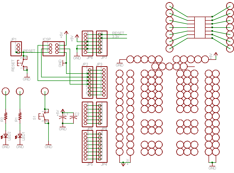
So I added two 3 pin connectors for the servos and a LED.
Here is an update to the schematic for the shield just incase someone want to critique it.
.
So I added two 3 pin connectors for the servos and a LED.
Here is an update to the schematic for the shield just incase someone want to critique it.
Attached Files
-
 Klotz_Netduino_Servo_Joystick_Shield-V14.pdf 29.26KB
22 downloads
Klotz_Netduino_Servo_Joystick_Shield-V14.pdf 29.26KB
22 downloads
-
Joystick_Shield-v12.pdf 14.63KB
18 downloads
#1061 Netduino servo class
Posted by
on 22 August 2010 - 03:26 PM
in
Netduino 2 (and Netduino 1)
I just tried to use the class from the post, and I get an error while compiling "Error 1 The type or namespace name 'Cpu' could not be found (are you missing a using directive or an assembly reference?)"Nice, at least someone got some use out of it! Yeah, this class has been used and tested extensively, so it's all worked out. I will be updating the class in just a sec, too.
While I am new to using C# this is not the first class library I have made so I am a little confused about why I am getting the error. I did copy and pasted the file from the post.
Any suggestion?
#1080 Netduino servo class
Posted by
on 22 August 2010 - 06:52 PM
in
Netduino 2 (and Netduino 1)
So it was a problem with the way I created the project, not the source at all. Once I went to References under the solution explorer and added the Microsoft.SPOT.Hardware, it build just fine.Did you include the Microsoft.SPOT.Hardware reference? You probably also need SecretLabs.NETMF.Hardware and SecretLabs.NETMF.Hardware.Netduino
Like I said I am still a nubie when it comes to C#.
BTW: That and SecretLabs.NETMF.Hardware. Oops.

Thanks.
#2144 Compatible Shields and Accessories
Posted by
on 11 September 2010 - 11:52 PM
in
Netduino 2 (and Netduino 1)
 )
)
Attached Thumbnails
#2145 Compatible Shields and Accessories
Posted by
on 12 September 2010 - 12:03 AM
in
Netduino 2 (and Netduino 1)

Attached Thumbnails


#2316 Analog Input problem
Posted by
on 14 September 2010 - 11:19 PM
in
Netduino 2 (and Netduino 1)
I just got my netduino and I'm starting to try to get analog input and I always get 0 when I read my pin(A0). Do you see anything I did wrong?
My setup looks like this
3.3->AREF
A0->Photo Resistor->GND
public class Program
    {
        public static void Main()
        {
            // write your code here
            InterruptPort tester = new InterruptPort(Pins.GPIO_PIN_A0, false, Port.ResistorMode.Disabled, Port.InterruptMode.InterruptEdgeBoth);
            tester.Dispose();

            AnalogInput apin0 = new AnalogInput(Pins.GPIO_PIN_A0);
            apin0.SetRange(0, 100);

            int test = 0;
            while (true)
            {
                Thread.Sleep(250);
                test = apin0.Read();
                Debug.Print("Test: " + test);
            }

        }

    }
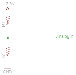
You would need another resister to 3.3Vdc to develop a voltage divider. There is no pull-up in the An-in.
#2318 Analog Input problem
Posted by
on 14 September 2010 - 11:41 PM
in
Netduino 2 (and Netduino 1)
First you need to know what the resistance of the photo resister is. Mine was 25k full dark.I'm confused would it look like
AREF+3.3v->resistor(what resistance?)->ground?->photo resistor->A0?
Second you need to decide if you want it to pull-up or pull-down. I used mine in a pull-up.
Then choose a resitance to give you some kind of reasonable current limit, I chose 10K since I just wanted to play.
So using the attached schematic, I put the photoresister in a R1, a 10k in R2, you can try it either way and pick the one you like.
Attached Thumbnails
#2321 Analog Input problem
Posted by
on 15 September 2010 - 12:49 AM
in
Netduino 2 (and Netduino 1)
The fun is just beginingThank you for explaining now i understand. Time to play with my netduino!
The next thing you want to do is check out the projects page.
#2330 Analog Input problem
Posted by
on 15 September 2010 - 10:55 AM
in
Netduino 2 (and Netduino 1)
My guess: CadSoft Eagle (?)
Yep, I use Cadsoft Eagle. But don't ask me for help with it. I am just returning to doing hardware after 40 years and am trying to catch up.I just kindof hack away with Eagle until something works.
#2408 Getting off to a good start with Netduino
Posted by
on 17 September 2010 - 10:23 PM
in
General Discussion
EDITTED---
I purchased an AdaFruit Protoshield and that's all build and piggybacking my Netduino. What's not clear to me is how the various buttons on the shield relate to the Netduino. For example, I have two LEDs on the protoshield and two buttons. How are these addressable through code (given that the Netduino only has one of each)?
EDITTED AGAIN--
What I'd like to do as a next step is control a 5v motor, attached to the shield, and have its speed adjusted with a photoresister. Pretty basic, eh? :-) I'm not clear on how/where I'd hook up the motor to the shield (which pins) and also where the photresistor fits into the picture (on the shield in series with the motor, presumably, but what voltages should I use)?
And again
Thanks.
Mark
I hope you don't mind I didn't quote your entire post since I am going to start by answering the easy parts
. But here goes:One of the buttons (the one labeled RESET) is tied to the reset on your board and that is all it can do for you.
The other button and the two LEDs are not assigned to any function instead they are tied to ground on one end and the other is to a pad you can route to any of the DIO ports. The LEDS have a current limiting resister on them so they are safe. You just have to make sure you define the DIOs used with the LEDs as outputports and the button as an input port with a pullup. You can view the schematic here: http://www.ladyada.n...v5schematic.png
#2411 Buzz a piezo speaker?
Posted by
on 18 September 2010 - 04:02 AM
in
Netduino 2 (and Netduino 1)
Try
  var period = (uint)(1000000 / frequency);
  pwm.SetPulse(period, period/2);
I used the same buzzer and I just checked my code and the period is in microseconds like I remembered.
#2422 Controlling a LED Intensity
Posted by
on 18 September 2010 - 01:03 PM
in
General Discussion

#2783 Stay close to your computer (or come to MakerFaire)...
Posted by
on 24 September 2010 - 05:58 PM
in
General Discussion
I noticed the spec's http://www.netduino....oplus/specs.htm say the microSD holds up to 2Gb. Is this because the Plus uses SPI to talk to the SD card or is it a software limit?Yes, and it's bedtime for sure
Chris

#3149 Experimental Drivers for Wiznet-based Ethernet Shields
Posted by
on 29 September 2010 - 01:22 AM
in
Beta Firmware and Drivers

#3158 Experimental Drivers for Wiznet-based Ethernet Shields
Posted by
on 29 September 2010 - 03:19 AM
in
Beta Firmware and Drivers
#3160 Experimental Drivers for Wiznet-based Ethernet Shields
Posted by
on 29 September 2010 - 03:47 AM
in
Beta Firmware and Drivers
I had read that DNS was not working, but I thought that was the purpose of the proxy in the following segment from the Wiznet test posted in this forum.Looking at your error code again... DNS is not supported yet. We put that in the release notes next to the download link, but maybe we need to make that more obvious. Can you try connecting via direct IP and see if that works?
Chris
            string url = "http://www.secretlabs.com/default.htm";
            // NOTE: since this experimental release does not support DNS yet, we must use the IP address of the web server as the proxy address.
            string proxy = "174.143.45.105"; // ip address of secretlabs.com

            // If the device must go through a proxy server, then set proxy to the
            // fqdn or ip of the proxy server.
            try
            {
                String html = GetWebPage(proxy, url, 80);
                Debug.Print(html);
            }
            catch (SocketException se)
BTW I don't require a proxy server to access the net.
#3163 Experimental Drivers for Wiznet-based Ethernet Shields
Posted by
on 29 September 2010 - 04:00 AM
in
Beta Firmware and Drivers
I fixed that error by updating PhysicalAddress initialization in the sample program with the MAC address printed on sticker on the back of my Ethernet Shield.
Replace the bytes in red with your actual MAC address.
networkInterface.PhysicalAddress = new byte[] { 0x01, 0x23, 0x45, 0x67, 0x89, 0x01 };
Good luck!
I have an Arduino Ethernet shield and there is no MAC address printed on it anywhere. Does the Wiz5100 have one "programmed" into it? If so how do I get it?


