Well, after a while waiting (including a UPS train derailment :-)), I finally got my Netduino today. All worked exactly as planned and within 15 minutes I'd run the blinking light demo and the event handler. All pretty simple. And now I have some questions...
I purchased an AdaFruit Protoshield and that's all build and piggybacking my Netduino. What's not clear to me is how the various buttons on the shield relate to the Netduino. For example, I have two LEDs on the protoshield and two buttons. How are these addressable through code (given that the Netduino only has one of each)?
How does the Port.ResisterMode work? Does this imply that I can turn on and off a resister associated with each pin? And if so, what resistence is involved?
I'm not clear on the various voltages available to me between the Netduino and the protoshield and what pins use what voltage. The analog pins use 3.3V input right? Anything above that can do damage?
What I'd like to do as a next step is control a 5v motor, attached to the shield, and have its speed adjusted with a photoresister. Pretty basic, eh? :-) I'm not clear on how/where I'd hook up the motor to the shield (which pins) and also where the photresistor fits into the picture (on the shield in series with the motor, presumably, but what voltages should I use)?
I like the event handler approach (as opposed to a while(true) loop. As a curiosity I'm wondering of there's any way to have the photoresister trigger the motor on and off only when it reaches a certain light level (= resistance) and if this can be done with event handlers. I'd like to detect this in software and take "some action" based on the resistence (like start the motor). How would I go about that without the while(true) loop?
I'm really looking forward to getting into this.
Thanks.
Mark

Getting off to a good start with Netduino
Started by MarkWill, Sep 17 2010 10:06 PM
2 replies to this topic
#2

klotz
-

- Members
-

- 60 posts
Advanced Member
Posted 17 September 2010 - 10:23 PM
EDITTED---
I purchased an AdaFruit Protoshield and that's all build and piggybacking my Netduino. What's not clear to me is how the various buttons on the shield relate to the Netduino. For example, I have two LEDs on the protoshield and two buttons. How are these addressable through code (given that the Netduino only has one of each)?
EDITTED AGAIN--
What I'd like to do as a next step is control a 5v motor, attached to the shield, and have its speed adjusted with a photoresister. Pretty basic, eh? :-) I'm not clear on how/where I'd hook up the motor to the shield (which pins) and also where the photresistor fits into the picture (on the shield in series with the motor, presumably, but what voltages should I use)?
And again
Thanks.
Mark
I hope you don't mind I didn't quote your entire post since I am going to start by answering the easy parts
 . But here goes:
One of the buttons (the one labeled RESET) is tied to the reset on your board and that is all it can do for you.
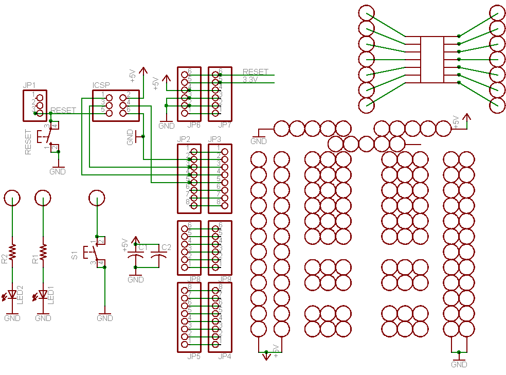
The other button and the two LEDs are not assigned to any function instead they are tied to ground on one end and the other is to a pad you can route to any of the DIO ports. The LEDS have a current limiting resister on them so they are safe. You just have to make sure you define the DIOs used with the LEDs as outputports and the button as an input port with a pullup. You can view the schematic here: http://www.ladyada.n...v5schematic.png
#3
Chris Walker
-

- Moderators
-

- 7767 posts
Secret Labs Staff
- LocationNew York, NY
Posted 18 September 2010 - 11:20 PM
Glad you got your Netduino safely, MarkWill. I hope nobody got hurt--train derailment?!?Well, after a while waiting (including a UPS train derailment :-)), I finally got my Netduino today. All worked exactly as planned and within 15 minutes I'd run the blinking light demo and the event handler. All pretty simple. And now I have some questions...
To add to what Klotz said...
You can enable or disable the pull-up resistor on each digital pin (pull-down is not supported by the Atmel ARM microcontroller used on the Netduino). One case where this is useful is with InputPorts... If you have a pin which is neither "high" nor "low" the weak pullup provided by this feature forces the line to be "high" by default. So then connecting the pin to ground will give a definitive "low/false" value.How does the Port.ResisterMode work? Does this imply that I can turn on and off a resister associated with each pin? And if so, what resistence is involved?
The digital pins can all take 0V-5VDC inputs. The analog pins are limited to 0V-3.3VDC input (assuming you've connected 3.3V to the AREF pin...if you connect a lower voltage like 2.6VDC to the AREF pin, then the analog inputs are limited to that voltage as their maximum).I'm not clear on the various voltages available to me between the Netduino and the protoshield and what pins use what voltage. The analog pins use 3.3V input right? Anything above that can do damage?
You'll want to use a bridge (as I believe Chris Seto mentioned in another thread). The PWM output on the line will drive the motor's speed--and the bridge will provide the necessary power to drive the motor (since the Netduino's pins can only drive about 8mA on average). If you want to drive "motor speed" with precision, servos can be a good option--you can control their "current position" digitally using PWM. Pins 5, 6, 9, and 10 can all act as PWM outputs (see the tech specs for features on each pin).What I'd like to do as a next step is control a 5v motor, attached to the shield, and have its speed adjusted with a photoresister. Pretty basic, eh? :-) I'm not clear on how/where I'd hook up the motor to the shield (which pins) and also where the photresistor fits into the picture (on the shield in series with the motor, presumably, but what voltages should I use)?
I'm really looking forward to getting into this.
One way to accomplish this is to create a timer that executes every ## milliseconds...and measure the light level in each run of the timer code. If it exceeds the desired light level, then you can change the PWM output to the motor. [You could also create a class that does this for you and raises events if you wanted].I like the event handler approach (as opposed to a while(true) loop. As a curiosity I'm wondering of there's any way to have the photoresister trigger the motor on and off only when it reaches a certain light level (= resistance) and if this can be done with event handlers. I'd like to detect this in software and take "some action" based on the resistence (like start the motor). How would I go about that without the while(true) loop?
Pretty exciting start... Please post pictures of what you build!
Chris


0 user(s) are reading this topic
0 members, 0 guests, 0 anonymous users


