bill.french's Content
There have been 260 items by bill.french (Search limited from 04-July 24)
#5165 Disposability
 Posted by
on 22 November 2010 - 03:43 AM
in
Netduino 2 (and Netduino 1)
Posted by
on 22 November 2010 - 03:43 AM
in
Netduino 2 (and Netduino 1)
This is how I started learning about it:
http://forums.netdui...ch__1#entry4293
#5149 LCDKeypad 16x2 HD44780 Shield
Posted by
on 21 November 2010 - 10:17 PM
in
Project Showcase
Can you elaborate on the keypad/analog input issue?
#5145 Ultrasonic Transducer
Posted by
on 21 November 2010 - 09:05 PM
in
General Discussion
What are you trying to do? This thread I'm sure has lots of good info:
http://forums.netdui...ch__1#entry4555
I would guess for motion detection, it's going to be hard to beat something like this for simplicity:
http://www.parallax....83/Default.aspx
#5095 How to tell Mini to auto start my app?
Posted by
on 20 November 2010 - 01:33 PM
in
Netduino Mini
Are you sure you are powering it properly? Sounds like the mini is only running off the ftdi power, if that's even possible?
#5008 Digital spirit-level, which sensor?
Posted by
on 17 November 2010 - 04:22 PM
in
General Discussion
Accelerometers generally should detect gravity as acceleration.
#4925 Measuring Analog Value and output it on console?
Posted by
on 15 November 2010 - 12:04 AM
in
General Discussion
This might help you:
http://forums.netdui...it-and-program/
#4904 Speed and turning control with Ardumoto - Motor Driver Shield
Posted by
on 14 November 2010 - 02:31 PM
in
General Discussion
Sorry I didn't notice originally! Just FYI, the "outofrange" exception made me think you were trying to access some capability outside of the range where it was possible.
#4901 Speed and turning control with Ardumoto - Motor Driver Shield
Posted by
on 14 November 2010 - 12:41 PM
in
General Discussion
I didn't catch this the first time, but I think PWM is only supported on pins 5,6,9,10 -- not 3 and 11.
Specs are here: http://www.netduino....duino/specs.htm
digital i/o features
● all 20 digital and analog pins: GPIO
● digital pins 0-1: UART 1 RX, TX
● digital pins 2-3: UART 2 RX, TX
● digital pins 5-6: PWM, PWM
● digital pins 7-8: UART 2 RTS, CTS
● digital pins 9-10: PWM, PWM
● digital pins 11-13: SPI MOSI, MISO, SPCK
● analog pins 4-5: I2C SDA, SCL
#4892 Speed and turning control with Ardumoto - Motor Driver Shield
Posted by
on 14 November 2010 - 12:07 AM
in
General Discussion
Your syntax is wrong:
PWM pwm1 = new PWM(Pins.GPIO_PIN_D3);
PWM pwm2 = new PWM(Pins.GPIO_PIN_D11);
I think is more what you want?
#4871 FPGA shield alpha
Posted by
on 12 November 2010 - 08:41 PM
in
Project Showcase
Ballpark, how much $$ are we talking about?
#4788 Netduino power
Posted by
on 10 November 2010 - 03:49 AM
in
General Discussion
Check this out:
http://forums.netdui...ch__1#entry3812
.. i'm thinking 15v should be fine.
#4778 Analog Input help...
Posted by
on 10 November 2010 - 12:37 AM
in
General Discussion
Are you talking about the http://fritzing.org/ diagrams? Fritzing is awesome.
#4764 Analog Input help...
Posted by
on 09 November 2010 - 08:09 PM
in
General Discussion
I'm sorry, I don't know, then. I added some to my shopping cart at sparkfun, if I get enough other stuff to make an order I'll try and get one hooked up to see how it works. I also updated my drawing to show a line from 3.3v to aref, but I don't think that has anything to do with it.
#4762 Analog Input help...
Posted by
on 09 November 2010 - 07:56 PM
in
General Discussion
and you're not using the far left (adj) pin at all, right?
#4760 Analog Input help...
Posted by
on 09 November 2010 - 07:31 PM
in
General Discussion
ok i think I got this right -- i believe the right most pin is the - and the center pin is the +:

Is that about what you're doing, with the multimeter/analog input hooked up after the resistor?
Is that about what you're doing, with the multimeter/analog input hooked up after the resistor?
#4756 MotorButton loop error? Update: Now more about Motor Driving.
Posted by
on 09 November 2010 - 07:12 PM
in
Visual Studio
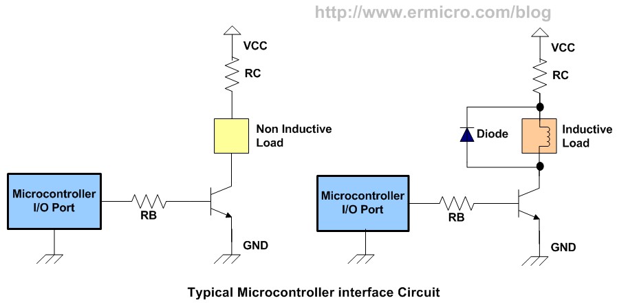
Yeah, that diagram is the same basically as the right side of what I posted.
Vbe is the base to emmitter voltage.
Vce is the collector to emmiter voltage.
Ib is the current to base
Ic is the current through the collector
RC is the resistor to the collector <--i just edited this, i had it wrong!
Since you're just going to be using the transistor as a switch, you really don't need to worry so much about any of those to get started. They will be whatever they are. All you need to really worry about is RB and maybe the diode. Starting with an RB of 1k is a good starting point.
If you want to think of the transistor as something more than a switch (because they are so much more) in this case, think of the transistor as a current multiplier. Different transistors have different multiplication factors (the real name of which escapes me...) .. so, if you put in say 1ma into the base (Ib), that will allow say 100x (which is typical of common transistors at radioshack) the current to move from the collector to the emmiter (Ic). If you use a 1k resistor for RB, that gives you .0005 amps for Ib, which should multiply to .5 amps Ic, which should be enough to drive your motor.
Some transistors:
http://www.radioshac...oductId=2062586
#4753 Analog Input help...
Posted by
on 09 November 2010 - 06:32 PM
in
General Discussion
Yeah, I don't know then -- using the 5v should be fine. Can you post a picture or a diagram or something? I wish I had one of those sensors to try it out myself.
#4752 Basic Analog Input Circuit and Program
Posted by
on 09 November 2010 - 06:31 PM
in
General Discussion
Sure! It's over in the netduino plus forum:
http://forums.netdui...er-the-network/
#4750 MotorButton loop error? Update: Now more about Motor Driving.
Posted by
on 09 November 2010 - 06:29 PM
in
Visual Studio
Here's what I would do. I am not an expert on anything so... you're on your own.
Looking at the below diagram, look at the circuit on the right, since a motor is an inductive load. I would skip RC, because I am hardcore. RB i would start with a 1k Ohm. I would use just about any NPN resistor, RadioShack should definitely have them, I think they sell a 10 count variety pack. For such a small motor almost any diode would do, something like this should be fine: http://www.radioshac...oductId=2036269
Is it safe to assume you understand the symbols in the diagram for the diode, transistor, etc?
#4749 Analog Input help...
Posted by
on 09 November 2010 - 06:15 PM
in
General Discussion
I'm sorry, I don't know. According to this picture:

If your room is 72 degrees F, which is 295 degrees K, you should have a reading of about 2.95V, I think.
When you're measuring with the multimeter, is the netduino involved in the circuit at all? I would start with the netduino out of the picture entirely a focus on getting the right readings on a multimeter, then focus on getting them well below 3.3V to be safe for the analog inputs.
#4748 want little help
Posted by
on 09 November 2010 - 06:08 PM
in
General Discussion
You could use something like this with the netduino:
http://www.parallax....83/Default.aspx
to sense the motion, which could then alert something to start recording, or raises some other sort of alert.
http://www.parallax....83/Default.aspx
to sense the motion, which could then alert something to start recording, or raises some other sort of alert.
#4746 Analog Input help...
Posted by
on 09 November 2010 - 06:04 PM
in
General Discussion
The analog input only supports 3.3v -- but if I'm reading this right, a reading of 4.88v equates to 488K, which is 419F, which is 215C ... so unless your house is on fire, something else is wrong.
#4704 MotorButton loop error? Update: Now more about Motor Driving.
Posted by
on 09 November 2010 - 01:48 AM
in
Visual Studio
do you have or can you get at least a transistor and some resistors? I think you risk hurting your netduino hooking it up directly.
#4703 Basic Analog Input Circuit and Program
Posted by
on 09 November 2010 - 01:41 AM
in
General Discussion
This post covers:
First, the circuit. You'll want to read about voltage dividers to really understand what is happening. The potentiometer acts as one of the resistors in the voltage divider -- and since a potentiometer's resistance changes by turning it, it provides a good source for the analog input. If you are comfortable with Ohms Law (V=IR) the wikipedia article on voltage dividers is pretty approachable in my opinion. Something important in the circuit is the link from 3.3v to the aref pin. Aref is "analog reference" and sets the ceiling of the analog input. The max is 3.3v. I believe the revision B netduino boards have an internal tie in so that using aref is optional.

... and what it might look like on a breadboard:

... and the program:
Basically, the program opens up an analog input port (a5 in this case), reads the value into a string, and prints the string to the output window in visual studio every 100ms. As you adjust the potentiometer, the values displayed in debug should change, varying from about 0 to about 1023, which are the bounds of the 10-bit ADC (analog-digital coverter) built in to the netduino.
Since I have a Netduino Plus, I have also set it up send the readings over the network and graph them in a Windows Forms Application, so I could see the results visually as I turned the potentiometer to different positions. It's important to realize that digital inputs read either 1 or 0; analog inputs have a range, and the graph from my netduino plus illustrates this:

If you don't have a netduino plus, you can cut and paste the data from the output window in Visual Studio into Excel or a Google spreadsheet and graph from there.
If this is interesting to you, I would encourage you to search the forums for "analog", "analoginput", and "setrange" for lots more useful information.
- a very basic circuit using a potentiometer
- a program for reading an analog input port
First, the circuit. You'll want to read about voltage dividers to really understand what is happening. The potentiometer acts as one of the resistors in the voltage divider -- and since a potentiometer's resistance changes by turning it, it provides a good source for the analog input. If you are comfortable with Ohms Law (V=IR) the wikipedia article on voltage dividers is pretty approachable in my opinion. Something important in the circuit is the link from 3.3v to the aref pin. Aref is "analog reference" and sets the ceiling of the analog input. The max is 3.3v. I believe the revision B netduino boards have an internal tie in so that using aref is optional.
... and what it might look like on a breadboard:
... and the program:
using System.Text;
using Microsoft.SPOT;
using System.Threading;
using SecretLabs.NETMF.Hardware;
using SecretLabs.NETMF.Hardware.Netduino;


namespace NDP_SocketSender1
{
    public class Program
    {
        public static void Main()
        {

            AnalogInput a5 = new AnalogInput(Pins.GPIO_PIN_A5);

            while (true)
            {
                string s = a5.Read().ToString();
                Debug.Print(s);
                Thread.Sleep(100);
            }
        }
    }
}
Basically, the program opens up an analog input port (a5 in this case), reads the value into a string, and prints the string to the output window in visual studio every 100ms. As you adjust the potentiometer, the values displayed in debug should change, varying from about 0 to about 1023, which are the bounds of the 10-bit ADC (analog-digital coverter) built in to the netduino.
Since I have a Netduino Plus, I have also set it up send the readings over the network and graph them in a Windows Forms Application, so I could see the results visually as I turned the potentiometer to different positions. It's important to realize that digital inputs read either 1 or 0; analog inputs have a range, and the graph from my netduino plus illustrates this:
If you don't have a netduino plus, you can cut and paste the data from the output window in Visual Studio into Excel or a Google spreadsheet and graph from there.
If this is interesting to you, I would encourage you to search the forums for "analog", "analoginput", and "setrange" for lots more useful information.
#4701 MotorButton loop error? Update: Now more about Motor Driving.
Posted by
on 09 November 2010 - 12:52 AM
in
Visual Studio
I'm pretty sure you're going to need at least a transistor and a diode to drive a motor -- i don't think the netduino (or most microcontrollers for that matter) can safely drive a motor.


