The Netduino forums have been replaced by new forums at community.wildernesslabs.co.
This site has been preserved for archival purposes only
and the ability to make new accounts or posts has been turned off.
MotorButton loop error? Update: Now more about Motor Driving.
Sorry to bother you all, but I seem to have run in to a bit of trouble. I get a strange exception windows when I press the button after I load the program on the netduino. The button is supposed to start the motor as long as it is being held down. I am not sure what I did wrong here... I seem to have forgotten my password to my youtube account, and to recover it you have to go to your email, which ironically I also forget. So, I can't upload the video of the error. Here is my code though.
using System;
using System.Threading;
using Microsoft.SPOT;
using Microsoft.SPOT.Hardware;
using SecretLabs.NETMF.Hardware;
using SecretLabs.NETMF.Hardware.Netduino;

namespace NetduinoApplication1
{
    public class Program

    {
        static OutputPort motor = new OutputPort(Pins.GPIO_PIN_D6, false);
        public static void Main()
        {
            InterruptPort button = new InterruptPort(Pins.ONBOARD_SW1, false, ResistorModes.Disabled, Port.InterruptMode.InterruptEdgeBoth);
            button.OnInterrupt += new NativeEventHandler(button_OnInterrupt);

            Thread.Sleep(Timeout.Infinite);
        }

        static void button_OnInterrupt(uint data1, uint data2, DateTime time)
        {
            PWM[] motor = new PWM[] { new PWM(Pins.GPIO_PIN_D6) };

            while (data2 == 0)
            {
                //Starts Motor 1
                motor[0].SetDutyCycle(100);

            };
        }

    }
}
Credits go to Oz-Solutions and whoever does the How-To's on the website section "Projects"
First of all, the event handler button_OnInterrupt is called when the button is pushed. Your loop that checks "while data2 = 0" will use the value of data2 passed into the event handler--not the actual state of the button.
I think what you really want there is:
while (button.Read() == 0)
In which case you'll also need the make the button a static variable and create it in the class instead of the Main() function.
When you say that you get strange exception errors, can you take a screenshot of what you're seeing and post it?
In addition to what Chris said, it would be good idea to enable glitch filter (pass 'true' to the InterruptPort constructor), and the 'while' loop is not really needed because the interrupt is trigerred by edges:
public class Program
{
  // Member variable to prevent garbage collection
  static InterruptPort button;

  // Instantiate here to keep interrupt handler code small
  static PWM motor = new PWM(Pins.GPIO_PIN_D6);

  public static void Main()
  {
    button = new InterruptPort(Pins.ONBOARD_SW1, true, ...);
    ...
  }

  static void button_OnInterrupt(uint pin, uint state, DateTime time)
  {
    if(state == 0)
    {
      // Falling Edge
      motor.SetDutyCycle(100); // On
    }
    else
    {
      // Rising Edge
      motor.SetDutyCycle(0); // Off
    }
}
I have to go soon, but here is the error. I think I am becoming a bit more familiar with C# and Mr. Netduino. NOTE: That I do get this right after I press the button.
Thank you both very much!
Sincerely,
Cwbh
In all likelihood, the cause of the exception is that you have already used the pin D6 in OutputPort instance (line #13 in the screenshot), so it cannot be used again in PWM object. Certain features require exclusive access to the pin, it'd have to be released (disposed) for reuse.
Okay, I got the code down with no errors, just two things... It doesn't turn the motor (Kind of a problem). I am not sure what CW2 means when it says "Falling Edge", "Rising Edge" and "Garbage collection"
Thanks a lot for your help guys.
Sincerely,
Cwbh
CODE:
using System;
using System.Threading;
using Microsoft.SPOT;
using Microsoft.SPOT.Hardware;
using SecretLabs.NETMF.Hardware;
using SecretLabs.NETMF.Hardware.Netduino;

namespace NetduinoApplication1
{
    public class Program
    {
        static InterruptPort button;
        static PWM motor = new PWM(Pins.GPIO_PIN_D6);

        public static void Main()
        {
            // write your code here
            button = new InterruptPort(Pins.ONBOARD_SW1, true, Port.ResistorMode.Disabled, Port.InterruptMode.InterruptEdgeBoth);

            button.OnInterrupt +=new NativeEventHandler(button_OnInterrupt);
        }

        static void button_OnInterrupt(uint data1, uint data2, DateTime time)
        {
            if (data2 == 0)
            {
                motor.SetDutyCycle(100);
            }
            else
            {
                motor.SetDutyCycle(0);
            }

        }

    }
}
Changed the code a bit; did I forgot to sleep it? Here is the new code. I made it so it would also light up the led when pressed.
using System;
using System.Threading;
using Microsoft.SPOT;
using Microsoft.SPOT.Hardware;
using SecretLabs.NETMF.Hardware;
using SecretLabs.NETMF.Hardware.Netduino;

namespace NetduinoApplication1
{
    public class Program
    {
        static InterruptPort button;
        static PWM motor = new PWM(Pins.GPIO_PIN_D6);
        static OutputPort led = new OutputPort(Pins.ONBOARD_LED, false);

        public static void Main()
        {
            // write your code here
            button = new InterruptPort(Pins.ONBOARD_SW1, true, Port.ResistorMode.Disabled, Port.InterruptMode.InterruptEdgeBoth);

            button.OnInterrupt += new NativeEventHandler(button_OnInterrupt);

            Thread.Sleep(Timeout.Infinite);

        }

        static void button_OnInterrupt(uint data1, uint data2, DateTime time)
        {
            led.Write(data2 == 0);
            if (data2 == 0)
            {
                motor.SetDutyCycle(100);
            }
            else
            {
                motor.SetDutyCycle(0);
            }

        }

    }
}
I'm pretty sure you're going to need at least a transistor and a diode to drive a motor -- i don't think the netduino (or most microcontrollers for that matter) can safely drive a motor.
I have a motor controller (shield), just as of right now I don't know how to program it...
Here is the manual http://www.robotshop...ual-dri0009.pdf it is L298N.
-Cwbh
Well, I don't have my tech kits with me and won't for 2 weeks, the earliest being in 2 days. I can pick some up though; I live about 2 blocks from a Radioshack {Lucky me }
P.S. I am now thinking I am doing this completely wrong, just I am not sure why I am thinking this. I need another breadboard... I think this is getting off thread topic... If that is okay with Chris
-Cwbh
I am not sure what CW2 means when it says "Falling Edge", "Rising Edge" and "Garbage collection"
The falling edge is name for high to low (1 -> 0) transition of a [digital] signal, rising edge mean transition from low to high (0 -> 1). The value of Netduino pin SW1 is logical high (3.3 V) when the switch is not pressed. When you press it, it causes the signal to change to logical low (0V) - this transition is the falling edge, the pin circuitry detects it and triggers the interrupt, which is then handled by .NET Micro Framework runtime that in turn calls the interrupt event handler. Similarly, when you release the switch, the signal level gets back to logical high, the rising edge is detected and the interrupt event handler is executed (because you have set InterruptMode.InterruptEdgeBoth).
The popular explanation of garbage collection is that it is a mechanism in .NET Framework that manages allocation and automatically releases unused memory. If you are interested in details (including the 'correct' definition), please have a look at articles by Raymond Chen.
I'm pretty sure you're going to need at least a transistor and a diode to drive a motor -- i don't think the netduino (or most microcontrollers for that matter) can safely drive a motor.
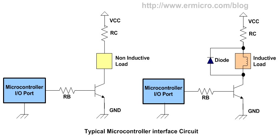
bill.french is right, you'd need to use a transistor (plus base resistor and flyback protection diode) to switch inductive load such as DC motor. Please have a look at the fourth image in Using transistor as a switch, or MOSFET switch example (replace lamp with the motor, you could use general purpose NPN transistor instead of MOSFET, but make sure it can handle the current).
Okay. I have looked at both links for diagrams. I see what it is doing, just I don't know what the variables are; this isn't a Legends. If I know what to buy I can put it together later today. Anyways, thanks a lot guys!
Sincerely,
Cwbh
Here's what I would do. I am not an expert on anything so... you're on your own.
Looking at the below diagram, look at the circuit on the right, since a motor is an inductive load. I would skip RC, because I am hardcore. RB i would start with a 1k Ohm. I would use just about any NPN resistor, RadioShack should definitely have them, I think they sell a 10 count variety pack. For such a small motor almost any diode would do, something like this should be fine: http://www.radioshac...oductId=2036269
Is it safe to assume you understand the symbols in the diagram for the diode, transistor, etc?
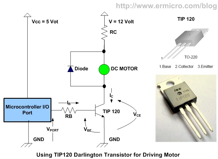
I thought that I would be this one, for motors. .I am not sure what Vbe is Ib and the other objects like RC. I can see the symbols like the diode, resistor, etc...
I can build circuits; I have done quite a few. Just I am not sure what those variables are. :/
Thanks a lot for your help though.
Sincerely,
Cwbh
P.S. Maybe this could go onto the "Motor control" in the project section? Just a thought.
Yeah, that diagram is the same basically as the right side of what I posted.
Vbe is the base to emmitter voltage.
Vce is the collector to emmiter voltage.
Ib is the current to base
Ic is the current through the collector
RC is the resistor to the collector <--i just edited this, i had it wrong!
Since you're just going to be using the transistor as a switch, you really don't need to worry so much about any of those to get started. They will be whatever they are. All you need to really worry about is RB and maybe the diode. Starting with an RB of 1k is a good starting point.
If you want to think of the transistor as something more than a switch (because they are so much more) in this case, think of the transistor as a current multiplier. Different transistors have different multiplication factors (the real name of which escapes me...) .. so, if you put in say 1ma into the base (Ib), that will allow say 100x (which is typical of common transistors at radioshack) the current to move from the collector to the emmiter (Ic). If you use a 1k resistor for RB, that gives you .0005 amps for Ib, which should multiply to .5 amps Ic, which should be enough to drive your motor.
Okay, I just bought the TIP 120, Assorted Rectifier Diodes, and 2n3906 PNP Transistors. I will get my breadboard tomorrow, and my resistors to see if it will work .
Thanks a lot for your guys help!
Sincerely,
Cwbh


 }
P.S. I am now thinking I am doing this completely wrong, just I am not sure why I am thinking this. I need another breadboard... I think this is getting off thread topic... If that is okay with Chris
-Cwbh
}
P.S. I am now thinking I am doing this completely wrong, just I am not sure why I am thinking this. I need another breadboard... I think this is getting off thread topic... If that is okay with Chris
-Cwbh