Netduino home hardware projects downloads community

Jump to content


The Netduino forums have been replaced by new forums at community.wildernesslabs.co. This site has been preserved for archival purposes only and the ability to make new accounts or posts has been turned off.

sweetlilmre's Content

There have been 62 items by sweetlilmre (Search limited from 24-May 23)


By content type

See this member's


Sort by                Order  

#1523 Variable length SPI

Posted by sweetlilmre on 30 August 2010 - 01:26 PM in Netduino 2 (and Netduino 1)

Hi,

I have a device that uses a SPI-like clock / data mechanism, however the transfer length depends on what form of command you are sending to the device. This makes standard SPI 8/16 bit transfers impossible. For certain commands though the device has a 'bulk' write option that is 8 bits wide.

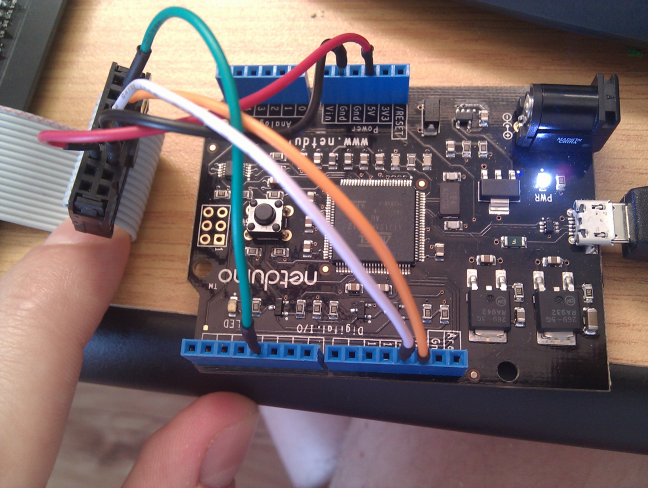
I have taken adavantage of this on a PIC by bit-banging in the non 8-bit commands and then using SPI to handle the bulk transfers. This really speeds up communication, but unfortunately I can't seem to replicate this behaviour on the NetDuino as once I initialise SPI the SPI pins are not longer available to write to manually i.e.

SPI.Configuration conf = new SPI.Configuration(Pins.GPIO_PIN_D4, false, 0, 0, false, true, 1000, SPI.SPI_module.SPI1);
SPI SPI_port = new SPI(conf);

OutputPort _clkPin = new OutputPort(Pins.GPIO_PIN_D13, true);

causes an exception CLR_E_PIN_UNAVAILABLE.

Is there someway to get around this or perhaps I am looking at this the wrong way?

Thanks in advance
-(e)


#1558 Variable length SPI

Posted by sweetlilmre on 31 August 2010 - 08:07 AM in Netduino 2 (and Netduino 1)

Hi sweetlilmre,

Thanks for the post and welcome to the Netduino community!

We're looking at adding variable-bit SPI as a feature in the Netduino firmware. If you want to make the modifications in the source code yourself, you're welcome to do so. You can find the source on the downloads page.

Chris


Hi, and thanks for the welcome, seems like a great community to be part of :)

I'll take a look at the the SPI stuff, but driver level code is an unknown for me at this point.
The device in question works, but slowly. I will release the code to drive it shortly and then upgrage to SPI when it becomes available.

Out of interest is there a reason why the SPI driver locks the SPI pins? Is this at the framework level i.e. unavoidable?
The reason I ask is that variable SPI could be implemented at the user level in an emulated context if this was not the case.

I know this is the worst kind of question, but do you have any info on:
  • A beta of the firmware with the variable SPI feature (I would be keen to assist in testing)
  • An estimation on release date

Thanks
-(e)


#1570 Netduino firmware with GCC 4.4

Posted by sweetlilmre on 31 August 2010 - 05:38 PM in Netduino 2 (and Netduino 1)

Hi Jeremy, CW2,

I used your patches and all works pretty much as expected. Just to confirm, the target firmware will still be too large and will require the fix mentioned above in the other thread?
I get:

c:\GCC\bin\arm-none-eabi-ld.exe: region `LR_FLASH' overflowed by 576 bytes

Does this match your build? If so, its a pity its such a small difference! :)

edit: CW2:

For clarity (on my part):

// flash page is 8KB
// ranges are inclusive i.e. 0-5 is 6 pages
const BlockRange g_SAM7X_BS_BlockRange[] =
{
	{ BlockRange::BLOCKTYPE_BOOTSTRAP,     	0,  5 }, // 0x00000 - ( 6*8*1024) 0x0C000, length 0x0C000
	{ MEMORY_BLOCKTYPE_GCC_SPECIAL_BOOTSTRAP,  6, 10 }, // 0x0C000 - (11*8*1024) 0x16000, length 0x0A000, Sum = 0x16000 (.bin size = 0x143B0)
	{ BlockRange::BLOCKTYPE_CODE,         	11, 44 }, // 0x16000 - (45*8*1024) 0x5A000, length 0x44000
	{ MEMORY_BLOCKTYPE_GCC_SPECIAL_CODE,  	45, 53 }, // 0x5A000 - (54*8*1024) 0x6C000, length 0x12000, Sum = 0x56000, Flash size = 0x542C0
	{ BlockRange::BLOCKTYPE_DEPLOYMENT,   	54, 60 }, // 0x6C000 - (61*8*1024) 0x7A000, length 0x0E000 -> 56 KiBi for application code
	{ BlockRange::BLOCKTYPE_STORAGE_A,    	61, 61 }, // 0x7A000 - (62*8*1024) 0x7C000, length 0x02000
	{ BlockRange::BLOCKTYPE_STORAGE_B,    	62, 62 }, // 0x7C000 - (63*8*1024) 0x7E000, length 0x02000
	{ BlockRange::BLOCKTYPE_CONFIG,       	63, 63 }  // 0x7E000 - (64*8*1024) 0x80000, length 0x02000
};

So therefore:

<Set Name="Code_BaseAddress"	Value="0x00116000"/>
<Set Name="Deploy_BaseAddress"  Value="0x0016C000"/>

And once I have this correct I should be able to flash?

also:

However, during my numerous experiments, I have found out that bootloader compiled with RVDS actually works with firmware compiled with GCC 4.4 (!), so it appears to be a better choice, as there is more memory left for the application code, because GCC bootloader is twice as big as RVDS one (~40 KiBi vs. ~80 KiBi). I will probably stick with this for now...


This would be nice :) any hints on how to accomplish it?
-(e)


#1627 HT1632 interface (alpha)

Posted by sweetlilmre on 01 September 2010 - 09:53 AM in Netduino 2 (and Netduino 1)

Hi,

Attached is some code to drive the HT1632 LED Matrix chip as found in the Sure Electronics DE-DP13212 and similar boards (Sure Electronics).
The code is horribly slow at the moment as a raw bit-bang approach is used to communicate with the HT1632 (and I am sure my horribly un-optimsed code does not help :))
I will migrate this to SPI once variable SPI is available. At any rate here it is to look at.

This code was ported from Miles Burton's Arduino code and is released under the same GPL license.

Any pointers on optimisation would be great as C# on an embedded device is very new to me!

Connection is 5 wires:
Power and ground to 5V and GND pins.
ChipSelect to digital pin 4
Clock to digital pin 13
Data (WR) to digital pin 12

Hope this helps someone. I will attempt to optimise this to make it useful and to support the 2416 boards as well.
-(e)

Attached Files


#1634 HT1632 interface (alpha)

Posted by sweetlilmre on 01 September 2010 - 04:36 PM in Netduino 2 (and Netduino 1)

Very cool! You've implemented "bit banged" variable-bit SPI using managed...doubly cool.


I really can't take too much of the credit, its mostly Miles Burton's code, but thanks :)
I think that is definitely part of the speed issue as is the memory access on the buffer arrays.

I need to have a look at that...
-(e)


#1736 Netduino Mini

Posted by sweetlilmre on 03 September 2010 - 01:30 PM in Netduino 2 (and Netduino 1)

Hi,

In as far as more inputs, would this help?
-(e)


#1778 BitBanger Driver

Posted by sweetlilmre on 05 September 2010 - 05:07 PM in Netduino 2 (and Netduino 1)

Hi,


UPDATE: this post has been updated with a newer version and firmware: 11/29/2010. This newer version provides SoftSPI like capabilities.

In my quest to make my HT1632 display useable I have developed a generic bit banger driver.

The attached archive unzips into the "MicroFrameworkPK_v4_1\Solutions\Netduino" dir.
If you want to build this yourselves you will have to build the managed solution and generate the client assemblies and then build the firmware as usual.

The speed increase in amazing when driving the HT1632 and I know that variable SPI is around the corner, but I thought this might be useful in a more generic context (the code should be device neutral).

The bit banger is constructed with a configuration class that describes two pins, one clock and one data.
Ownership of the pins then belongs to the BitBanger class.

public class Config
{
public Config( Cpu.Pin clockPin,
             		bool clockEdgeRising,
             		Cpu.Pin dataPin,
             		Cpu.Pin latchPin,
             		bool latchActiveState )
}

BitBang.Config config = new BitBang.Config( clkPin, true, dataPin );
// set data & clock pin modes
BitBang bb = new BitBang( config );


Additionally the latchPin and latchActiveState Config members allow for additional flexible latching behaviour.

public enum LatchBehaviour
{
	PerTransfer,
	Per8Bits,
	Per16Bits,
	Per32Bits,
	Never
}

LatchBehaviour is passed to the block blitting function and will toggle a latch line (or CS possibly) in a certain manner.
This is very useful for writing to shift registers in a continuous mode.


The BitBang class interface has some basic functionality:

These two methods bang out a stream of bytes, with each byte written from the MSb (bigEndian) or LSb and with optional latch behaviour.

public void Write( byte[] writeBuffer, int writeOffset, int writeCount, bool bigEndian)
public void Write( byte[] writeBuffer, int writeOffset, int writeCount, bool bigEndian, LatchBehaviour latchBehaviour )


And these two methods bang out up to 32 bits with the same endian functionality as above.

public void Write32( UInt32 data, byte numBits, bool bigEndian )
public void Write32AndLatch( UInt32 data, byte numBits, bool bigEndian )


I have attached 2 files containing the compiled firmare (tinyclr.hex.zip) and the source code (bitbang.zip).
Included in the source code is the compiled client assembly which you will find under the MicroFrameworkPK_v4_1\Solutions\Netduino\ManagedCode\SecretLabs_NETMF_Hardware\bin\Release dir.
You will need to reference this assembly or replace the one provided with the NetDuino SDK in order to use the BitBang class.

:D :D :D

Hope this is interesting / useful
-(e)

Attached Files


#1834 BitBanger Driver

Posted by sweetlilmre on 06 September 2010 - 05:03 AM in Netduino 2 (and Netduino 1)

Oh hey, that is really cool. If a few community members have feedback on uses for this, maybe we could integrate something like this into the stock firmware in a future update?

Chris


Thanks! Maybe this could be built into a namespace with CW2's OneWire stuff? A kind of bitbanger toolkit?

Is there anyway to ship a driver without including it in a matching kernel i.e. have the native and managed portions separate and loadable or is built-in the only possibility?

Also I can trim down the code more, and put it in a better more generic namespace. Do you have a namespace suggestion?

edit: any news on a GIT source share or something similar for the firmware? It would make community generated patches so much nicer and easier :)

-(e)


#2605 Talking to 74HC574 chips

Posted by sweetlilmre on 22 September 2010 - 09:43 AM in Project Showcase

Hi,

Here is a nice little R.E. project I did over the weekend on some old electronics: My Blog
There is so much old stuff just getting tossed into the dump which is a shame as these bits contain a wealth of commercial grade electronics.

-(e)


#2613 Talking to 74HC574 chips

Posted by sweetlilmre on 22 September 2010 - 04:37 PM in Project Showcase

Wow!
It always amazes me how well people can reverse engineer circuits. Well done!


Very nice, sweetlilmre!

We may need to have a "junkyard" challenge in the future :)


Thanks :) It was a good bit of fun and luckily not too difficult. There is a newer model of this decoder with a totally different display circuit / bus that I want to look at next. Only one 7-segment display, but 3 buttons and an IR receiver... this one looks challenging!

Hmm a Junkyard challenge sounds excellent....
-(e)


#2614 Netduino Serial Port Code Review

Posted by sweetlilmre on 22 September 2010 - 04:44 PM in Project Showcase

This is awesome :) Let us know how the locking code goes, and can you tell me what you used to do the video? It looks really good and would be a nice alternative to a blog post for me to try out sometime. Thanks -(e)


#2659 HT1632 interface (alpha)

Posted by sweetlilmre on 23 September 2010 - 10:00 AM in Netduino 2 (and Netduino 1)

Cool stuff Sweetlilmre!

I'm trying your sample with some of my 0832 boards here but I can't seem to get anything displayed on it. I have to say it are the green 0832's from SureElectronics and not the red ones don't know if that makes any difference. Just to be sure this is how I mapped the pins

NetDuino -------------- Matrix
Pin4 -------------- Pin3
Pin13 -------------- Pin5
Pin12 -------------- Pin7

Is that correct? or did I screw up :)


Hi,

Checking the 0832 Datasheet, your connections look good.
I assume you have also wired:

NetDuino GND to Matrix 11
NetDuino 5V to Matrix 12

Also that you have set the dip switches on the back of the matrix to 1=ON, 2=OFF, 3=OFF, 4=OFF?

Make sure you have the matrix connector orientation correct (I got it upside down the first time and wired 5V to GND... :))
-(e)


#2669 HT1632 interface (alpha)

Posted by sweetlilmre on 23 September 2010 - 01:18 PM in Netduino 2 (and Netduino 1)

Very strange, I did connect GND to pin 11 and 5V to 12 on the matrix, I also checked the CS selection switch and only 1 is on.. I have also some 2416 boards I tried one of those still no luck! Do you have a picture or something on how you wired yours? Or do you have any other ideas?

Thanks!


Does this help at all?

Posted Image

I just rewired it and tested it out. It all seems to work OK?
On the ribbon side, the pins are:

Green: Chip Select, pin3
Orange: Clock, pin5
White: Data, pin 7
Black: GND, pin 11
Red: 5V, pin 12

The 2416 will not work as the addressing mode is different. (well it might display something, but certainly not what is intended, I must get one of those to play with though...)

HTH

-(e)


#2677 OneWire ALPHA

Posted by sweetlilmre on 23 September 2010 - 03:37 PM in Beta Firmware and Drivers

Does anybody from those who downloaded the firmware and possibly tried it have any feedback? How should I interpret the silence, with regard to initial eager requests? Please let me know whether it works or not with your device, so I can fix possible problems and publish the code. Thanks in advance.


Hi,

I have been meaning to look at this but I only just found a 1-wire supplier. I should be able to get hold of some sensors next week and I'll give it a go.

Looks like fun!
-(e)


#2699 HT1632 interface (alpha)

Posted by sweetlilmre on 23 September 2010 - 09:56 PM in Netduino 2 (and Netduino 1)

Thanks for the picture! My configuration is exactly the same! So it can't be the wiring, you said the 2416 won't work because of a different pixel mapping.. I have read somewhere that the pixel mapping of the green 0832 is different from the red 0832 too just like the green 2416 pixel mapping is different from the red one.

The code runs just fine I have checked if the matrices are getting power. I really have no idea what is going wrong.

This is what is on the back of my 0832: Posted Image

Is that the same as yours?

Thanks again for your help! I really hope I can get it to work!


I can't imagine the mapping is different if they are using the same display driver... I have the Yellow one btw.
Here is a close up (sorry about the washed out look, but the lighting in my study is terrible at night)

Posted Image
The only other thing I can suggest is that you have a bad connection. My clock line was dodgy initially and nothing would display.

HTH
-(e)


#2713 $10 GPS receiver?!

Posted by sweetlilmre on 24 September 2010 - 06:23 AM in General Discussion

I've always wanted to interface a GPS receiver with Arduino/Netduino, but the $60 price tag stopped me.
Then I remember the GPS device that came with old Microsoft Streets and Trips.
I realize that the Netduino cannot act as a host for the USB GPS device, but how difficult would it be to gut it out and hook it up to the Netduino?

There's quite a few of these old GPS receivers on ebay. Here's an example of one that sold for $10 shipping included.
http://cgi.ebay.com/...b#ht_500wt_1154


Hi,

I would seem that you are not the first to think of this :)
Interestingly enough the USB dongle is a converter, so if you get that you get a free USB to TTL converter!
(see the pic in the Yahoo link)


I have one of those receivers. It's pretty accurate, I like it.

EDIT: It might also be a GPS360


This might be the alternative pinout for the 360: GBA GPS

I am going to buy one of these right now! :)

-(e)


#2723 $10 GPS receiver?!

Posted by sweetlilmre on 24 September 2010 - 07:42 AM in General Discussion

See: http://mfgps.codeplex.com

This is a community GPS project. We are currently looking for devs to write the GPS parsing methods. I think I'll start a separate thread on this, as a matter of fact.


Looks good. If I can find some devices I will contribute / test. Unfortunately it seems the $10 mark is not achievable :(
-(e)


#2874 HT1632 interface (alpha)

Posted by sweetlilmre on 25 September 2010 - 12:44 PM in Netduino 2 (and Netduino 1)

Well I'm going to give up for now I tried everything, I cut a connector from one of the cables and soldered the pins directly to it but I can't seem to get anything out of it.


I have 8 matrices and tried them all no luck with all of them. I really do not hope it is my netduino that is faulty or something.

I'm going to order a red 0832 matrix from sure to see if that one works for me..

One other thing I have thought of.. did you change anything in your firmware? maybe I have an older firmware or something? or isn't that possible, i'm such a newbee with Netduino :)


Hi,

Damn this is frustrating! :)

I run custom firmware for the bitbanger mod I made but this should not be a issue (the code attached is the original code I developed on stock firmware).

Do you by any chance have an Arduino? If so try the code from Miles Burton (linked in the first post) with your matrix and see if that works.

As a last option I reflashed with the original firmware to make sure there were no funnies there:
4.1.0.3 firmware

Then rebuilt the attached code and deployed it, it runs as expected. Try and do the firmware update, just in case. I have a watch on this topic so post back when you get the red matrix. I'd love to see this resolved!
Now to reflash back to custom... :)

-(e)


#2891 LCD Library

Posted by sweetlilmre on 25 September 2010 - 06:39 PM in Project Showcase

Hi,
I have finally published the library on CodePlex. You can grab it here http://microliquidcr...l.codeplex.com/
Basically the same code as previously published on my blog, just with few renames.

Please let me know if you have any suggestions on what can be improved.


Hi,

Thanks for the brilliant library :)
I just soldered up a pc1602f display in direct GPIO mode and it all works nicely.

As a tip for anyone else doing this, if you don't have a pot of the correct value, you can just tie Vo to ground for maximum contrast (this had me stumped for a bit, I thought the display was broken :))

On Monday hopefully I will have my shift registers and I can try it with that.
-(e)


#2918 HT1632 interface (alpha)

Posted by sweetlilmre on 26 September 2010 - 11:26 AM in Netduino 2 (and Netduino 1)

Whoot Whoot! Solved it! I tried the link you provided with the 4.1.0.3 firmware flashed the firmware and after the upgrade was finished I instantly saw something displayed on my Matrix!!

So the solution was flashing the updated firmware, now I have the same result as in the video posted earlier but the with my Netduino!

Thanks a million for helping me out! I will now try to make some extra functionality to run more than one display for example.. or do you have more recent code?


YAYAYAYAY!! :) Awesome!

I have some more recent code that uses the custom bitbanger firmware to really blast the display (it so much faster its unbelievable).
I need to fix it up so that compilation is conditional i.e. you don't need special firmware, and I have optimised the font drawing and some other bits.
I'll take a look tonight and see if I can post it up.

-(e)


#2919 Netduino Tip 04: Foam Board Project Base

Posted by sweetlilmre on 26 September 2010 - 11:28 AM in Project Showcase

Hi, What a great idea! :) I wonder if I can get this stuff in South Africa... hmmmm Also, could you tell me where you got those nice jumper wires from? I have some generic ones and they are OK, but yours look much nicer. Thanks -(e)


#3003 Netduino Tip 04: Foam Board Project Base

Posted by sweetlilmre on 27 September 2010 - 09:47 AM in Project Showcase

Thanks.
I got those jumper wires from China through ebay. I don't remember which seller exactly, but this cable looks like the one I have.
http://cgi.ebay.com/...=item1c1555b5ef

Lower quality compared to the one from Sparkfun, but also a lot cheaper!
I really like having different colored wires. Makes the circuit easier to "read".


Thanks, ordered some :) Now to find the foam board...
-(e)


#3299 Netduino IR Distance Sensor

Posted by sweetlilmre on 30 September 2010 - 08:37 PM in Project Showcase

I have drivers for the FEZ to run all the sharp distance sensors accurate to within a few mm, if anyone's interested i can port them over to Netduino, however i don't have one to test on (yet).


Yes please :) I just got one today that I would like to start playing with soon. Or just post the code and I'll convert it?
-(e)


#3705 LCD Library

Posted by sweetlilmre on 09 October 2010 - 09:04 AM in Project Showcase

Hi,

First off with respect to my previous reply: tie-ing Vo to ground only works for certain displays. I have 2, one works and one just shows black blocks i.e. the contrast it too high.

Secondly I have built the shift register circuit but my wiring was totally different to Szymon's and so I need to alter the code to allow a different pin assignment. I have implemented a dynamic mapping system that should allow any wiring configuration.

Please see attached code.

The BaseShifterLiquidCrystalTransferProvider now makes use of a ShifterSetup class which handles the pin mapping.

Setup (which you can find in the test program) looks like this:

  	// 2. use shift register provider
  	ShifterSetup setup = new ShifterSetup();
  	setup.AssignBit( ShiftBit.Q0, LCDPin.BL );
  	setup.AssignBit( ShiftBit.Q1, LCDPin.DB7 );
  	setup.AssignBit( ShiftBit.Q2, LCDPin.DB6 );
  	setup.AssignBit( ShiftBit.Q3, LCDPin.DB5 );
  	setup.AssignBit( ShiftBit.Q4, LCDPin.DB4 );
  	setup.AssignBit( ShiftBit.Q5, LCDPin.E );
  	setup.AssignBit( ShiftBit.Q6, LCDPin.RW );
  	setup.AssignBit( ShiftBit.Q7, LCDPin.RS );

  	var lcdProvider = new Shifter74Hc595LiquidCrystalTransferProvider( setup, SPI_Devices.SPI1, LED_Latch_Pin,
                                                         				Shifter74Hc595LiquidCrystalTransferProvider.
                                                           				BitOrder.MSBFirst );

Also in the test program I fixed the CreateCharTest() test method to clear the screen before writing the custom character, which seems to make it work properly on my display.


Thanks

Edit:

Here is a pic of my circuit:

Posted Image
-(e)


#3769 LCD Library

Posted by sweetlilmre on 11 October 2010 - 04:43 PM in Project Showcase

I am having trouble getting this to work I have used the code, and followed the wiring instructions here. I cant get the LCD to do anything other then turn on. Here is a picture of my current set up. Those LEDs just stay on/off as they are in the picture, and they should be flashing I think.

Any idea as to what I am doing wrong?

Thanks for your help


Firstly it looks like your contrast is at 100% (the completely white blocks would indicate this).
Try to just apply power (no signals lines) and turn the contrast down until the blocks almost disappear.

Secondly the Fritzing wiring diagram on Szymon's blog page is slightly incorrect w.r.t. the SPI port:

SHCP = PIN 13 (not 12)
STCP = PIN 10
DS = PIN 11

Thirdly which source are you using, Szymon's original or mine? If mine, have you configured the pin mappings correctly?

HTH
-(e)

Edit: one more thing you can try, once you have checked my points above is to change the MSB / LSB orientation of Szymon's code (if you are using his code). I had to change this to get my stuff working.


home    hardware    projects    downloads    community    where to buy    contact Copyright © 2016 Wilderness Labs Inc.  |  Legal   |   CC BY-SA
This webpage is licensed under a Creative Commons Attribution-ShareAlike License.