I just read you were thinking of changing to kail MDK last year? Are you going to switch to Keil MDK Still?
stotech's Content
There have been 12 items by stotech (Search limited from 24-May 23)
#62737 Native Development Options?
 Posted by
on 19 May 2015 - 05:40 AM
in
Netduino 3
Posted by
on 19 May 2015 - 05:40 AM
in
Netduino 3
#62736 Native Development Options?
Posted by
on 19 May 2015 - 04:55 AM
in
Netduino 3
I've heard that RVDS is extremely expensive. What version do you use. I would like to get a quote. Would it make debugging and modifying native neduino code much easier. I'm really in need of adapting it to STM32F407IGT6.
Thanks
#62047 Compiling Custom Firmware. emIDE?
Posted by
on 07 April 2015 - 12:31 AM
in
Netduino Plus 2 (and Netduino Plus 1)
Thankyou. Thankyou Thankyou! your a legend, That fixed it.
#62017 Compiling Custom Firmware. emIDE?
Posted by
on 04 April 2015 - 07:12 AM
in
Netduino Plus 2 (and Netduino Plus 1)
I've been trying to learn how to port cause i want to make a netduino with more pins using the STM32F407IG. I've read for days and followed tons of guides, but can't get any cmd line compilers to run using any guide. see the following. Not sure if it's cause i'm under windows 8?
C:\Porting\NP2\NetduinoPlus2>setenv_base.cmd GCC4.7.2  c:\yagarto
Compiler: GCC4.7.2 c:\yagarto
The system cannot find the path specified.

C:\Porting\NP2\NetduinoPlus2>Msbuild Solutions\NetduinoPlus2\dotnetmf.proj /T:re
build /p:flavor=release;tcp_ip_stack=lwip /filelogger
'Msbuild' is not recognized as an internal or external command,
operable program or batch file.
Trust me it's there. But doesn't work even if i use the GCC compiler from CW2's guide.
Then i found this program called emIDE. It was actually recommended on the yagarto site. It seems super stable and has a pretty nice gui. So i tryed compiling with that but get a couple of warnings during the build. But it doesn't seem to spit out any files? Does anyone have time to try it out. might be worth looking into a nicer gui compiler. If not I'd really appreciate any help getting started with why those other compilers weren't working.
Thanks in advance.
#62046 Garbage Collector, SD Card, Stream Writer, Ram
Posted by
on 07 April 2015 - 12:30 AM
in
Netduino Plus 2 (and Netduino Plus 1)
Thanks A heap. I'll mull over this with my mate google for a few days and see if i can make use of it.
#62024 Garbage Collector, SD Card, Stream Writer, Ram
Posted by
on 06 April 2015 - 12:03 AM
in
Netduino Plus 2 (and Netduino Plus 1)
Please Help!
I'm running out of ram all the time when i try and write to the SD card, But it says I've got heaps spare. Here is my code.
public static void Writer(string msg, string path, string file)
        {
            Debug.GC(true);
            Debug.Print("mem:  " + Debug.GC(true));

            lock (CardLock)
            {
                //SDC_flushSlow();
                int bufferSize = msg.Length;

                Debug.Print("Attempting to write with buffer of " + bufferSize.ToString());

                try
                {
                    if (Detect.SD_Card() & File.Exists(path + file))
                    {
                        using (var writestream = new FileStream(path + file, FileMode.Create, FileAccess.ReadWrite, FileShare.ReadWrite, bufferSize))
                        {
                            StreamWriter SW = new StreamWriter(writestream);
                            SW.Write(msg);
                            SW.Flush();
                            SW.Close();
                        }
                    }
                    else if (Detect.SD_Card())
                    {
                        if (!Directory.Exists(path))
                        {
                            Directory.CreateDirectory(path);
                        }
                        using (var writestream = new FileStream(path + file, FileMode.Create, FileAccess.ReadWrite, FileShare.ReadWrite, bufferSize))
                        {
                            StreamWriter SW = new StreamWriter(writestream);
                            SW.Write(msg);
                            SW.Flush();
                            SW.Close();
                        }
                    }
                }
                catch (Exception e)
                {
                    Debug.Print("SD_Writer Failed " + e.Message);
                }

                DebugLED.Show(15, 500);
            }
        }
But I get this every time.
SDC_Flushed and remounted
mem: 24732
Attempting to write with buffer of 1074
Failed allocation for 343 blocks, 4116 bytes
Failed allocation for 343 blocks, 4116 bytes
A first chance exception of type 'System.OutOfMemoryException' occurred in System.IO.dll
SD_Writer FailedException was thrown: System.OutOfMemoryException
Ok, I�ve got an idea that might be causing it. Do you think that it could be that I have about three threads running at this stage?
if I call this:
Debug.GC(true)
Debug.Print("mem: " + Debug.GC(true));
Then it says I have 24k spare.
But the it can�t find a 4k in a row to open the stream writer.
Could it be that the 2 other threads are preventing the garbage collector from moving memory objects. Does the garbage collector run across all threads or only the one it is called in?
Thanks So much in advance.
#62027 Garbage Collector, SD Card, Stream Writer, Ram
Posted by
on 06 April 2015 - 09:44 AM
in
Netduino Plus 2 (and Netduino Plus 1)
Thanks for that detailed response. The program continues to run fine even though the writer fails. So I'm assuming it's a problem finding sequential RAM as opposed to any RAM. Does everything i declare in managed code get "pinned"? Is there a way to pre-allocate memory for a managed function. Or do i just need to go over the code i've got.
#62861 Compiling Firmware with Keil evaluation.
Posted by
on 25 May 2015 - 04:58 AM
in
Netduino Plus 2 (and Netduino Plus 1)
Hi everyone. I�ve got keil installed and I�ve challenged myself to compile the firmware for the NP2. From there I�ll try and make the changes needed to get it working on an STM32F407IGT6
Here is what I�ve done so far.
Prerequisites:
- Visual Studio 2012 or both .NET Framework 4.0 and Windows SDK for Windows
- .NET Micro Framework Porting Kit 4.3 QFE1
- Netduino 2 Firmware v4.3.1 source
How to build the firmware with Keil;
� Install Keil eval (you need to email them to arrange a trial). Mine installed to C:\keil_v5
� Install .NET Micro Framework Porting Kit 4.3 QFE1 (C:\MicroFrameworkPK_v4_3)
� Make a folder C:\Porting
� Copy C:\MicroFrameworkPK_v4_3 to C:\Porting\PK_v4_3
� Extract Netduino 2 Firmware v4.3.1 source to C:\Porting\NP2_v4_3
� Make a folder C:\Porting\Mixed
� Copy �C:\Porting\PK_v4_3� to �C:\Porting\Mixed� overwrite all.
� Copy �C:\Porting\NP2_v4_3� to �C:\Porting\Mixed� overwrite all.
� Navigate to C:\Porting\Mixed\Solutions\NetduinoPlus2\TinyBooter and make a copy of scatterfile_bootloader_rvds.xml. Rename it to scatterfile_bootloader_mdk.xml. (We might have to make some changes to this later???)
� Launch cmd.exe (note: I can�t use Msbuild in cmd.exe. For some reason I need to launch C:\ProgramData\Microsoft\Windows\Start Menu\Programs\Microsoft Visual Studio 2012\Visual Studio Tools\ VS2012 x86 Native Tools Command Prompt) I don�t know why?
� Use these commands
cd porting\mixed
setenv_base.cmd MDK5.14 PORT C:\keil_v5
Msbuild Solutions\NetduinoPlus2\dotnetmf.proj /T:rebuild /p:flavor=release;tcp_ip_stack=lwip /filelogger
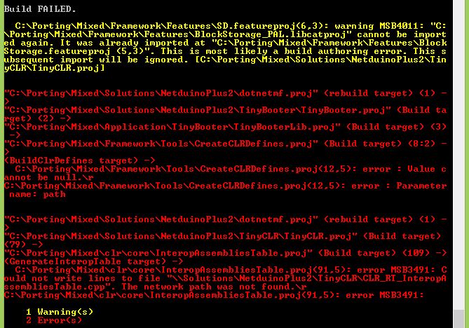
And this is where I�m up to.
Only 2 Errors, (see attached file) I�m appealing to the community to help me finish this guide.
Thanks in advance.
Attached Thumbnails
#62880 Compiling Firmware with Keil evaluation.
Posted by
on 26 May 2015 - 05:15 AM
in
Netduino Plus 2 (and Netduino Plus 1)
OK. I thought i had the solution
https://www.ghielect.../topic?id=15600
by changing the command from
setenv_base.cmd MDK5.14 PORT C:\keil_v5
to
setenv_mdk.cmd 5.14 C:\keil_v5
Turns out that produces 115 errors???
#64345 LCD-Boost library for Netduino
Posted by
on 20 October 2015 - 11:23 PM
in
Project Showcase
Thanks Again Mario. I thought that might be the case. But thanks for confirming it.
#64329 LCD-Boost library for Netduino
Posted by
on 19 October 2015 - 02:57 AM
in
Project Showcase
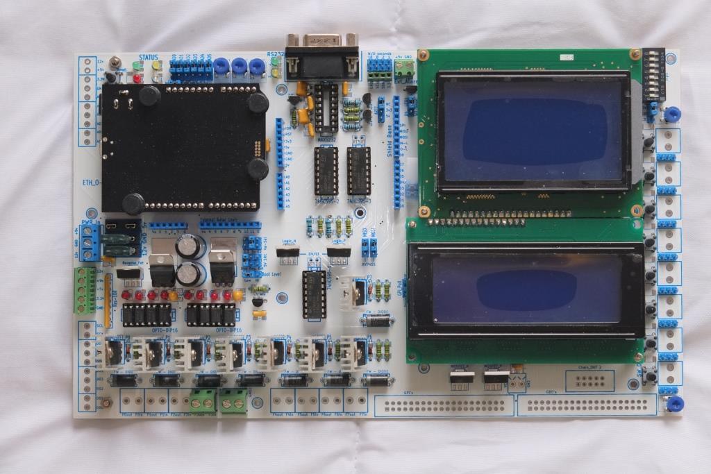
Not sure if this will get picked up cause this post is pretty old. I really need to get some more performance out of a HD44780 I'm using over spi. I'm just using the stefan's .netmftoolbox at the moment to drive it using the 74hc595 class. I thought the perfomance would be ok except that it is not really. I've got the code copied into my project but have to change it because the wiring is different on the custom PCB i have made. can anyone help me modify the code to allow for my different wiring? Bit_shifting is a little out of my depth. All though, come to think of it. I would still need to use the 74ch595 class because the are three 595's in the chain. if I were to go and use the spi directly it would write random stuff to the next 2 chips in the chain. Which brings me to the next question. would using this display driver get me anymore performance. seeing that It would have to write to the spi over the 74hc595 class from the netmftoolbox anyway. Anybody?
//#define CRONO

using System;
using Microsoft.SPOT;
using Microsoft.SPOT.Hardware;
using System.Threading;

using Cet.HW.GDI;

/*
 * Copyright 2012, 2013 by Mario Vernari, Cet Electronics
 * Part of "Cet Open Toolbox" (http://cetdevelop.codeplex.com/)
 *
 * Licensed under the Apache License, Version 2.0 (the "License");
 * you may not use this file except in compliance with the License.
 * You may obtain a copy of the License at
 *
 *     http://www.apache.org/licenses/LICENSE-2.0
 *
 * Unless required by applicable law or agreed to in writing, software
 * distributed under the License is distributed on an "AS IS" BASIS,
 * WITHOUT WARRANTIES OR CONDITIONS OF ANY KIND, either express or implied.
 * See the License for the specific language governing permissions and
 * limitations under the License.
 */
namespace Cet.HW.Drivers
{
    /// <summary>
    /// Driver for a generic HD44780-based character-matrix LCD module.
    /// It takes advantage of the DMA SPI's buffer-transfer,
    /// achieving a very good performance
    /// </summary>
    /// <remarks>
    /// See HD44780 specs at: http://www.adafruit.com/datasheets/HD44780.pdf
    /// For the char-maps see: http://web.alfredstate.edu/weimandn/lcd/lcd_addressing/lcd_addressing_index.html
    /// </remarks>
    public sealed class BoostHD44780
        : ICompositionRenderer//, IDisposable
    {
        //some ready-to-use display configurations
        public static readonly LayoutConfig Layout16x2 = new LayoutConfig
        {
            LogicalSize = 0x0210,
            PhysicalColumns = 0x10,
            PhysicalRow0 = 0x00000000,
            PhysicalRow1 = 0x00000100,
        };

        public static readonly LayoutConfig Layout20x4 = new LayoutConfig
        {
            LogicalSize = 0x0414,
            PhysicalColumns = 0x14,
            PhysicalRow0 = 0x02000000,
            PhysicalRow1 = 0x03000100,
        };


        //bit-masks for the control pins of the LCD module
        private const int LcdEnable = 0x40;
        private const int LcdRead = 0x20;
        private const int LcdRegSel = 0x10;

        //codes defined for the HD44780 interfacing
        private const int LcdSendCommand = 0x80;
        private const int LcdSendData = 0x80 | LcdRegSel;
        private const int LcdSetFunc8 = LcdSendCommand | 0x03;  //set DL=8 bit
        private const int LcdSetFunc4 = LcdSendCommand | 0x02;  //set DL=4 bit

        private const uint LcdSendDataMask =
            unchecked((uint)(LcdSendData * 0x1010101)) |
            (LcdEnable * 0x10001);

        private const uint LcdSendCommandMask =
            unchecked((uint)(LcdSendCommand * 0x1010101)) |
            (LcdEnable * 0x10001);

        //character map's address displacement between rows
        private const int AddressStep = 0x40;

        //the SPI's clock frequency in kHz
        //NOTE: the HD44780 execution time is about 37us (max)
        //A 600KHz setting allows a decent speed
        //together with a good reliability
        private const uint SpiClockRate = 400;  //avoid greater


        /// <summary>
        /// Create an instance of driver
        /// </summary>
        /// <param name="cspin">The output port used for the SS signal</param>
        public BoostHD44780(
            Cpu.Pin cspin,
            LayoutConfig config)
        {
            this.Height = config.LogicalSize >> 8; //rows
            this.Width = (byte)config.LogicalSize; //columns

            //a "physicalRow" is kinda row that can be written sequentially
            //to the LCD module, by taking advantage of its auto-increment
            //that is, a contiguous-address array of characters
            //each physicalRow is made of one or two "physicalBlocks"
            //a "physicalColumns" is the size of a physicalBlock
            this._physicalColumns = config.PhysicalColumns;
            this._physicalRow0 = config.PhysicalRow0;
            this._physicalRow1 = config.PhysicalRow1;

            //this indicates how many visible rows takes a single physicalRow
            int physicalBlocks = (config.PhysicalRow0 < 0x10000) ? 1 : 2;
            this._buffer = new byte[config.PhysicalColumns * physicalBlocks * 4 + 4];   //all phy-cells + 1 cmd

            //defines the first SPI slave device configuration
            this._spiConfig = new SPI.Configuration(
                cspin,             // SS-pin
                false,             // SS-pin active state
                0,                 // The setup time for the SS port
                0,                 // The hold time for the SS port
                true,              // The idle state of the clock
                true,              // The sampling clock edge (this must be "true" for the 74HC595)
                SpiClockRate,      // The SPI clock rate in KHz (avoid faster speed)
                SPI_Devices.SPI1   // The used SPI bus (refers to a MOSI MISO and SCLK pinset)
            );
        }


        private readonly SPI.Configuration _spiConfig;
        private int _lastHash;

        //related to the data exchange
        private readonly byte[] _buffer;
        private int _bufferIndex = -1;

        //some physical mapping info about the LCD layout,
        //such as the rows displacement, interleaving, etc.
        private readonly int _physicalColumns;
        private readonly int _physicalRow0;
        private readonly int _physicalRow1;

#if CRONO
        private OutputPort _test2 = new OutputPort(Pins.GPIO_PIN_D2, false);
#endif


        /// <summary>
        /// Gets the actual number of rows managed
        /// for the connected LCD module
        /// </summary>
        public readonly int Height;


        /// <summary>
        /// Gets the actual number of columns managed
        /// for the connected LCD module
        /// </summary>
        public readonly int Width;


        /// <summary>
        /// Init the LCD module
        /// </summary>
        private void Init()
        {
            /**
             * According to the HD44780 specs (page 46), the init for
             * 4-bit interface should be done as follows:
             * - the chip could be either in the 8-bit mode, or in the 4-bit
             *   depending on the power-on status
             * - send just a byte, then wait at least 4.1 ms
             * - send another a byte, then wait at least 100 us
             *   doing so the chip is always under control, regardless its mode
             * - send one byte, and immediately the byte for the 4-bit mode
             * - the chip is now working in 4-bit mode
             **/
            this._bufferIndex = 0;
            this.WriteByte(LcdSetFunc8);
            this.Send();    //this yields a small pause
            Thread.Sleep(4);

            this.WriteByte(LcdSetFunc8);
            this.Send();    //this yields a small pause
            Thread.Sleep(1);

            this.WriteByte(LcdSetFunc8);
            this.WriteByte(LcdSetFunc4);

            //at this point the HD44780 is working in 4-bit mode

            //complete the init
            WriteCommand(0x28); //set 2 rows (and 4-bit mode again)
            WriteCommand(0x0C); //turn on the display
            WriteCommand(0x06); //inc cursor, but don't shift the display
            WriteCommand(0x02); //return home

            this.Send();
        }


        /// <summary>
        /// Defines the pattern for a custom character
        /// </summary>
        /// <param name="code">The character code which the pattern is related to</param>
        /// <param name="pattern">The bit pattern which defines the aspect</param>
        /// <remarks>
        /// There are up to 8 codes available for custom characters:
        /// the codes span from 0 to 7, inclusive.
        /// Upon the display type, a character can be composed either
        /// by a 5x8 pixel matrix (most common), or a 5x10 pixel matrix.
        /// However, the most bottom row is reserved for cursor.
        /// Also see the HD44780 datasheet
        /// </remarks>
        /// <example>
        /// Suppose you would like to define the following
        /// 5x7 custom pattern for the code 0x02:
        ///
        ///     #####
        ///     #
        ///     #
        ///     ###
        ///     #
        ///     #
        ///     #
        ///
        /// Note: each '#' symbol is actually a pixel
        ///
        /// The related code to define the pattern will be:
        /// <code>
        ///     driver.DefineCustomCharacter(
        ///         0x02,   //the address of the character
        ///         new byte[7] { 0x1F, 0x10, 0x10, 0x1C, 0x10, 0x10, 0x10 }
        ///         );
        /// </code>
        /// </example>
        public void DefineCustomCharacter(
            int code,
            byte[] pattern)
        {
            //checks for driver initialization
            if (this._bufferIndex < 0)
            {
                this.Init();
            }

            int address = 0x40 + ((code << 3) & 0x38);
            WriteCommand(address);

            int count = pattern.Length;
            if (count > 10)
                count = 10;

            for (int i = 0; i < count; i++)
                WriteData(pattern[i]);

            this.Send();
        }

#if false
        /// <summary>
        /// Dump the entire local cache to the physical LCD module
        /// </summary>
        /// <param name="cache">The logical video-cache to be dumped</param>
        public void Dump(LcdBoostVideoCache cache)
        {
            //physical row #0 (always present)
            int row = this._physicalRow0;

            int address = 0x80;
            WriteCommand(address);

            this.DumpPhysicalRow(
                cache,
                (short)row,
                (row >> 16));

            //physical row #1
            if ((row = this._physicalRow1) != 0)
            {
                address += AddressStep;
                WriteCommand(address);

                this.DumpPhysicalRow(
                    cache,
                    (short)row,
                    (row >> 16));
            }
        }
#endif

        /// <summary>
        /// Performs a dump of single physical row
        /// </summary>
        /// <param name="cache"></param>
        /// <param name="block0"></param>
        /// <param name="block1"></param>
        private void DumpPhysicalRow(
            byte[][] cache,
            int block0,
            int block1
            )
        {
            this.DumpPhysicalBlock(
                cache[block0 >> 8],
                (byte)block0);

            if (block1 != 0)
            {
                this.DumpPhysicalBlock(
                    cache[block1 >> 8],
                    (byte)block1);
            }

            this.Send();
        }


        /// <summary>
        /// Deploys the data for the dumping of a single physical block
        /// </summary>
        /// <param name="vrow"></param>
        /// <param name="offset"></param>
        private void DumpPhysicalBlock(
            byte[] vrow,
            int offset)
        {
            for (int idx = offset, count = this._physicalColumns + offset; idx < count; idx++)
                this.WriteData(vrow[idx]);
        }


        /// <summary>
        /// Perform the buffer transfer to the LCD module
        /// </summary>
        /// <remarks>
        /// This function resets the buffer index
        /// </remarks>
        private void Send()
        {
            //open the SPI using the specified configuration,
            //manage the buffer transfer, finally release the port
            using (var spi = new SPI(this._spiConfig))
            {
                spi.WriteRead(
                    this._buffer,
                    0,
                    this._bufferIndex,
                    this._buffer,
                    0,
                    0,
                    0);
            }

            //reset buffer index
            this._bufferIndex = 0;
            System.Math.Cos(4.5);
        }


        /// <summary>
        /// Compose the bytes-pattern for sending the specified command
        /// to the LCD module
        /// </summary>
        /// <param name="value">The command to be sent</param>
        private void WriteCommand(int value)
        {
            uint magic =
                LcdSendCommandMask |
                (uint)(value >> 4) |
                (uint)((value & 0x0F) << 16);

            Utility.InsertValueIntoArray(
                this._buffer,
                this._bufferIndex,
                4,
                magic);

            this._bufferIndex += 4;
        }


        /// <summary>
        /// Compose the bytes-pattern for sending the specified data
        /// to the LCD module
        /// </summary>
        /// <param name="value">The data to be sent</param>
        private void WriteData(int value)
        {
            uint magic =
                LcdSendDataMask |
                (uint)(value >> 4) |
                (uint)((value & 0x0F) << 16);

            Utility.InsertValueIntoArray(
                this._buffer,
                this._bufferIndex,
                4,
                magic);

            this._bufferIndex += 4;
        }


        /// <summary>
        /// Compose the bytes-pattern for latching just a nibble (4 bits)
        /// to the LCD module (ref to the 74HC595 schematic)
        /// </summary>
        /// <param name="data">The encoded nibble to be sent</param>
        private void WriteByte(int data)
        {
            this._buffer[this._bufferIndex + 0] = (byte)(data | LcdEnable);
            this._buffer[this._bufferIndex + 1] = (byte)data;

            this._bufferIndex += 2;
        }


        #region ICompositionRenderer members

        CompositionTargetBase ICompositionRenderer.CreateTarget()
        {
            return new CompositionTargetHD44780(
                this.Width,
                this.Height);
        }


        void ICompositionRenderer.Dump(CompositionTargetBase composition)
        {
            //checks for driver initialization
            if (this._bufferIndex < 0)
            {
                this.Init();
            }

            //checks whether something in the cache has changed
            var target = composition as CompositionTargetHD44780;
            int hash = target.GetCacheHash();
            if (hash == this._lastHash)
                return;
            else
                this._lastHash = hash;

            //physical row #0 (always present)
            int row = this._physicalRow0;

            int address = 0x80;
            WriteCommand(address);

            this.DumpPhysicalRow(
                target.GetBuffers(),
                (short)row,
                (row >> 16));

            //physical row #1
            if ((row = this._physicalRow1) != 0)
            {
                address += AddressStep;
                WriteCommand(address);

                this.DumpPhysicalRow(
                    target.GetBuffers(),
                    (short)row,
                    (row >> 16));
            }
        }

        #endregion


        #region Driver config

        public struct LayoutConfig
        {
            public short LogicalSize;
            public byte PhysicalColumns;
            public int PhysicalRow0;
            public int PhysicalRow1;
        }

        #endregion

    }
}
#60690 Guidance: using 5V signals with pull-ups/pull-downs
Posted by
on 12 November 2014 - 04:05 AM
in
General Discussion
Yes, Yes Yes! I think this is my problem I keep having.
Is it only a problem if i enable the pullup on the specific pin with the 5v signal. As in,
If I use an internal pullup on a single pin that is attached to a 3.3v device.
Does this mean I can't attach a 5v device to a different pin and use an external pullup? Meaning that once the pull up is enabled on one pin, 5v is out for all other pins. Or is it just pin specific.
If that makes sense.
Thanks in advance.


