Netduino home hardware projects downloads community

Jump to content


The Netduino forums have been replaced by new forums at community.wildernesslabs.co. This site has been preserved for archival purposes only and the ability to make new accounts or posts has been turned off.
Photo

High Amp Relays?

Relays

  • Please log in to reply
9 replies to this topic

#1 JamieDixon

JamieDixon

    Member

  • Members
  • PipPip
  • 25 posts
  • LocationCary, NC

Posted 06 May 2013 - 12:59 PM

I am using some wheelchair motors controlled by a netduino and I have already smoked a couple of relays that only support up to 10 Amps (here).  It was fun (if not smelly) to learn that relays need to support both voltage AND amps.


In the Arduino forms, several people are using the Sabertooth 2X25 (here) relays that support up to 25 Amps.  The problem is that it is $125.


Does anyone know of some inexpensive relays that can support 25 amps?


Thanks in advance.


#2 Paul Newton

Paul Newton

    Advanced Member

  • Members
  • PipPipPip
  • 724 posts
  • LocationBerkshire, UK

Posted 06 May 2013 - 02:25 PM

Hi Jamie,


Have you considered using solid state control instead of relays?


With a relay you have no control over the current into the motor (all or nothing).

With solid state you can use PWM to ramp up the current gently.


Just a thought - Paul


#3 JamieDixon

JamieDixon

    Member

  • Members
  • PipPip
  • 25 posts
  • LocationCary, NC

Posted 06 May 2013 - 02:27 PM

No, I didn't!  Do you have a suggestion of an inexpensive Netduino SS Relay that can handle the 25 amps?


#4 hanzibal

hanzibal

    Advanced Member

  • Members
  • PipPipPip
  • 1287 posts
  • LocationSweden

Posted 07 May 2013 - 10:28 AM

Sorry for marching in like this, but wouldn't a MOSFET be an alternative solution here?


There are MOSFETs capable of handling 70A or even more and as far as I know they are pretty fast but characteristics changes as frequency reaches the order of megahertz. Also MOSFETs are usually much cheaper than solid state relays.


If you need galvanic isolation, I think it would be possible to use an optocoupler to control the MOSFET.


Need I say, I like MOSFETs?

:)


#5 JamieDixon

JamieDixon

    Member

  • Members
  • PipPip
  • 25 posts
  • LocationCary, NC

Posted 07 May 2013 - 10:48 AM

Thanks for marching Hanzibal!  I will check it out and see if there are some Arduino/Netdunio MOSFETs available.


#6 CW2

CW2

    Advanced Member

  • Members
  • PipPipPip
  • 1592 posts
  • LocationCzech Republic

Posted 07 May 2013 - 11:09 AM

Sabertooth 2X25 (here) relays that support up to 25 Amps.  The problem is that it is $125.

 
Sabertooth is not "relays", it is complete motor controller with many features, like various motor operation modes (differential, independent), can control speed and direction, accepts input from analog, R/C or serial protocols etc.


You might want to check out for example high-power motor drivers at Pololu, or you can build your own (H-bridge) driver from discrete MOSFETs or specialized driver IC. Also, don't forget to account for motor stall current, make sure the controller can survive it, and also spikes during motor startup, braking etc.


I would not recommend using relay to switch high current load, because it will wear out due to contact arcing.


#7 hanzibal

hanzibal

    Advanced Member

  • Members
  • PipPipPip
  • 1287 posts
  • LocationSweden

Posted 07 May 2013 - 11:11 AM

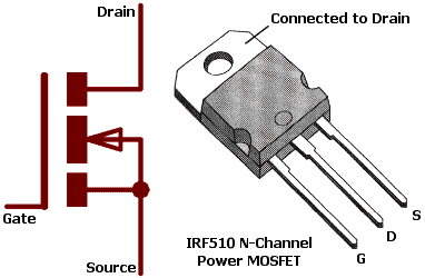
MOSFETs are general purpose components and not specific to Netduino/Android. Symbol and typical package usually looks like this:


Posted Image


Here's a isolated circuit I came up with just now. As I'm not at all sure that it's correct, I think it would be a good idea to hear Paul's or other's opinion before you try it:


Attached File  MOSFET.jpg   34.11KB   25 downloads


This would basically be a simple and very cheap motor driver that you can feed with PWM from your Netduino. You might need a small heat sink on the MOSFET and a diode over drain/source to protect from reverse current spikes from the motor.


If you don't want isolation, it would be much simpler. Note that you have to figure out the values of R1 and R2 to limit current through the optocoupler which usually can't take more than some 50mA. These values depend on the voltage of the high power side.


...or you can get a ready made high power DC motor driver like this one that can take 43A:

http://www.ebay.com/...=item27cd664268


Posted Image


I think the above driver even let's you switch direction on the motor. The Sabertooth is much more expensive plus I don't think you need all the features it has.


#8 Paul Newton

Paul Newton

    Advanced Member

  • Members
  • PipPipPip
  • 724 posts
  • LocationBerkshire, UK

Posted 07 May 2013 - 06:11 PM

As Hanzibal picked up, I was thinking of transistor control rather than a solid state relay module.


With the large currents you are trying to control I would tend towards using a ready made motor driver module or shield.

Someone else will have thought about getting thick enough tracks and the heat dissipation, etc.


CW2's Pololu link looks good - full H bridge control with high currents in a range of voltages. Half the price of the Sabertooth and a lot more sensible than trying to start from scratch.


Even with a module, you will need to do some homework!

Pay attention to the correct use of heat sinks - you will never hurt a circuit by ensuring it can't get too hot.

You need to implement current sensing - when the motors stall, the current sensing circuit should cut power to prevent a short circuit.

Make sure you have fuses on the battery for when things don't go as planned.

Check whether the motor driver circuit allows both sides of the bridge to be turned on at the same time (short circuit) - some more simple ones do allow this!. If it does, make sure the Netduino can't power on both halves at once (e.g. at power on / boot when the GPIOs may be puled high by weak pullups).

Use nice thick copper wire so the power is used in the motor and not the supply leads.


Remember to have fun - Paul


#9 hanzibal

hanzibal

    Advanced Member

  • Members
  • PipPipPip
  • 1287 posts
  • LocationSweden

Posted 07 May 2013 - 06:21 PM

That's a bunch of useful info right there. Paul, would my simplistic design work the addition of a hall effect sensor to shut down pwm when the motor stalls?

#10 Paul Newton

Paul Newton

    Advanced Member

  • Members
  • PipPipPip
  • 724 posts
  • LocationBerkshire, UK

Posted 08 May 2013 - 05:14 PM

That's a bunch of useful info right there. Paul, would my simplistic design work the addition of a hall effect sensor to shut down pwm when the motor stalls?

I guess you could do it with a Hall effect probe as the current sensor, but it would need some experimentation to get it working correctly. I would be worried that there might not be enough magnetic field to give a good result - you might end up with a very low trigger point because the sensor is not sensitive enough. Its a nice idea to have a contactless sensor. The "normal" method would to have a high amp low ohm resistor between the power transistors and ground. Many of the H-bridge driver chips are configured to allow this. The voltage accross the resistor is then proportional to the current, too high may indicate a stall. Put the voltage into a comparator and you have an interrupt for your processor. For extra safety (maybe you don't trust the processor to react fast, or are worried the PWMs could get stuck high), if you latch the comparator output with some gates, it can be used to shut off the PWM until the processor resets the latch. Hope this gets you thinking - Paul


Also tagged with one or more of these keywords: Relays

0 user(s) are reading this topic

0 members, 0 guests, 0 anonymous users

home    hardware    projects    downloads    community    where to buy    contact Copyright © 2016 Wilderness Labs Inc.  |  Legal   |   CC BY-SA
This webpage is licensed under a Creative Commons Attribution-ShareAlike License.