Netduino home hardware projects downloads community

Jump to content


The Netduino forums have been replaced by new forums at community.wildernesslabs.co. This site has been preserved for archival purposes only and the ability to make new accounts or posts has been turned off.

Paul's Content

There have been 14 items by Paul (Search limited from 19-April 23)


By content type

See this member's

Sort by                Order  

#5160 Deriving Angle Of Rotation From A MEMS Gyroscope

Posted by Paul on 22 November 2010 - 01:45 AM in Project Showcase

As part of my first effort to build an autonomous mobile robot platform “from the ground up” using the Netduino microcontroller I’ve spent a great deal of time reading about and exploring various strategies for obstacle avoidance. One of the issues I’ve been attempting to address is how to “turn” a moving robot in a determinate and repeatable manner to go around an object found to be in its path based on information returned by its on board sensors.

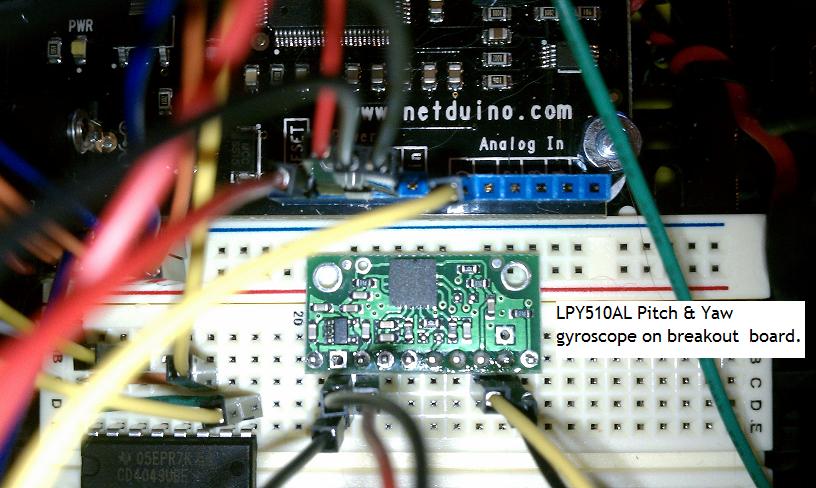
The robotic platform I am using for this project is the Pololu RP5 Robot Chassis. I chose it because it comes preassembled with two motors, gear trains and an AA battery pack at a very reasonable price. It is a very flexible platform in that one can add and stack a number of expansion plates to mount components on it. The current stage of construction incorporates the Netduino microcontroller, three Maxbotix LZ-EV0 ultrasonic sensors – one forward facing and one on each side facing outward at a 90 degree angle to the direction of travel, a Sparkfun Serial LCD which is used to display data of interest during tests. The newest addition is an STMicroelctrionics LPY510AL dual axis pitch and yaw +/- 100/400 degrees/second MEMS gyroscope. This gyroscope is factory calibrated at 3v so it is perfectly suited for the Netduino. My main interest in the gyroscope is for detecting the yaw, rotation about the vertical axis passing through the center, when the RP5 chassis turns. I purchased the LPY510AL from Pololu, they sell it all ready mounted to a very nice breakout/carrier board with the “ST” recommended filtering and voltage regulating components in place; the gyro itself is a very tiny surface mount device, soldering it to a carrier looks to be more of a challenge than I’m interested in.

The first thing that one needs to understand about a MEMS gyroscope is that it reports the angular rate of rotation along each axis, i.e. how fast it is rotating, and not the angle that it has rotated about each axis. The results of attempting to derive a simple and straightforward method to calculate the angle of rotation about each axis is what I would like to present.

The “LPY5” reports angular rate on each axis as an analog voltage. When at rest, that is the gyro is not undergoing movement along any of its axis’, the spec sheet states that it will output a voltage level of 1.23v referred to as the “zero-rate level." The spec sheet also states that: “Zero-rate level of precise MEMS sensors is, to some extent, a result of stress to the sensor and therefore zero-level can slightly change after mounting the sensor onto a printed circuit board or after exposing it to extensive mechanical stress. This value changes very little over temperature and time.”

After soldering a header to the “LPY5” carrier board, plugging it into a breadboard and powering it up I checked the “zero-rate level” with a digital multimeter. I found the at rest voltage to be reported as 1.248v, certainly reasonable. Rotating the breadboard by hand in a counter clockwise direction, to the left, showed an increase in the output voltage representing a positive angular rate and rotating the breadboard in a clockwise direction, to the right, showed a decrease in the output voltage representing a negative angular rate.

I connected the “LPY5” to the Netduino 3.3v power, ground and an analog input pin. I also connected the AREF pin to 3.3v. I wrote a very simple class for the “LPY5,” which appears below. It should be noted that when the class is instantiated it is assumed that the gyroscope is at rest. Under this assumption I set the variable “atRestVref” to the reported “zero rate” voltage level to be used in calculating the angular rate when the gyroscope is rotating. The angular rate about the “Z” axis, yaw, at any given moment is returned by the “AngularRate()” function. I am using the “LPY5” over the range of +/- 400 degrees/sec. Over this range the gyroscope has a sensitivity of 2.5mv / degree / sec. Thus to calculate the angular rate one would use the formula:

((voltage output of “LPY5”) - (at rest output voltage output of “LPY5”)) / (2.5mv )/ degrees / sec.

If one works through this word formula carefully, it will be seen that the various units of the coefficients cancel out and one is left with a number which represents “degrees/second” which is the angular rate. It should also be noted that I am not concerning myself with what is referred to as “gyroscopic drift” or the need to do temperature compensation for the gyro because I am only going to be taking isolated readings at distinct points in time.

using System;
using System.Threading;
using Microsoft.SPOT;
using Microsoft.SPOT.Hardware;
using SecretLabs.NETMF.Hardware;
using SecretLabs.NETMF.Hardware.Netduino;
using Math = System.Math;
 

namespace PoluluRobot_010
{
    class XZGyro
    {
        private Cpu.Pin inputPin { get; set; }
        private AnalogInput analogInput { get; set; }
        public double vRef { get; set; }
        public double atRestVRef { get; set; }

        public XZGyro(Cpu.Pin analogInputPin)
            {
                this.inputPin = analogInputPin;
                this.analogInput = new AnalogInput(inputPin);
                this.vRef = 3.3;
                this.atRestVRef = (vRef / 1023.00) * (Convert.ToDouble(analogInput.Read().ToString()));
            }

        
        public double AngularRate()
        {
            return (((vRef / 1023.00) * (Convert.ToDouble(analogInput.Read().ToString())) - atRestVRef) / .0025);
        }

    }
}


From a formal mathematical perspective one would find the actual angle of rotation around an axis of the gyroscope by integrating the angular rate over time. In reading through academic papers on robotic navigation with MEMS gyroscopes one will find some very elegant mathematics using quaternions, Heun’s method for integration, etc. However, I am not attempting to build an inertial navigation system and I’m really not sure of the Netduino’s ability to actually execute such complex algorithms in “real time.” At the same time if one thinks about integration conceptually, they will recall that it is about finding the area under a curve by taking the sum of the areas of a collection of rectangles which fill in the area under the curve. As the number of rectangles is increased to more closely fill in the space below the curve, the computed area becomes closer to the actual area. Perhaps an oversimplification but it should do.

My approach to the problem of deriving the actual angle of rotation from the angular rate reported by the gyroscope was that if I could get a large number of angular rates recorded over a period of time with the time duration of each sample being very small, I should be able to get a reasonable approximation of the angle of rotation for the gyroscope of the period of time. For any one sample the angle of rotation of the gyroscope is the (time duration of the sample) * (reported angular rate during of the sample). As the time duration of the samples becomes smaller the number of samples over any period of time increases and the results should become more accurate.

To establish a timer for the sample intervals I used the “Systems.Diagnostics.Stopwatch” class presented by Chris Walker in August. Since my specific goal was to control the turning angle of my robotic chassis I started out by attempting to define a “while” loop which would keep the chassis turning until a rotation of the desired number of degrees was completed. Inside the loop I would continuously take rate of rotation readings, multiply them by the duration of the reading to compute the angle of rotation for that sample and keep a running total of them. Once the running total of the angles of rotation was greater than or equal to the desired angle, the while loop ends. The result is the code below. Please note that the motorConroller class is a class I created for the Pololu Qik2s9v1 dual serial motor controller which is used to control the two motors in the chassis. The “TurnLeft” and “TurnRight” commands take an input parameter which represents a motor speed in the Pololu protocol.

using System;
using System.Collections;
using System.IO.Ports;
using System.Threading;
using Microsoft.SPOT;
using Microsoft.SPOT.Hardware;
using SecretLabs.NETMF.Hardware;
using SecretLabs.NETMF.Hardware.Netduino;
using System.Diagnostics;

namespace PoluluRobot_010
{

   
    public class Program
    {
        static XZGyro yaw_gyro = new XZGyro(Pins.GPIO_PIN_A0);
        static Stopwatch turnTimer = Stopwatch.StartNew();

        static SerialIinput serialInput = new SerialIinput();

        static InterruptPort interruptPort = new InterruptPort(Pins.ONBOARD_SW1, false, Port.ResistorMode.PullUp, Port.InterruptMode.InterruptEdgeLow);

        static DualSerialMotorController motorController = new DualSerialMotorController();


        static OutputPort crtlMaxbotixCenter = new OutputPort(Pins.GPIO_PIN_D7, false);
        static OutputPort crtlMaxbotixLeft = new OutputPort(Pins.GPIO_PIN_D8, false);
        static OutputPort crtlMaxbotixRight = new OutputPort(Pins.GPIO_PIN_D9, false);

        static double currentTimeStamp = 0;
        static double lastTimeStamp = 0;
        static double angleTurned = 0;
        static string ctrDist = "";
        static string lftDist = "";
        static string rgtDist = "";
        static Int16 currRgtDist = 0;
        static Int16 initRgtDist = 0;


        public static void Main()
        {
            
            turnTimer.Start();
            motorController.TurnLeft(50); 
            while (angleTurned < 90.0)
            {
                currentTimeStamp = turnTimer.ElapsedMilliseconds;
                angleTurned = angleTurned + (((currentTimeStamp - lastTimeStamp) / 1000) * yaw_gyro.AngularRate());
                lastTimeStamp = currentTimeStamp;
            }
            motorController.Stop();
            turnTimer.Stop();
            turnTimer.Reset();
            lastTimeStamp = 0;
            using (var s = serialInput)
            {
                s.ClearDisplay();
                Thread.Sleep(50);
                s.Print(angleTurned.ToString());
            }


In the second attachment is a screen shot of a portion of the list of values captured in the above “while” loop. The first column of numbers is the duration of the sample in seconds, the second column is the recorded angular rate – degrees/second. The last pair of numbers, outlined in red, show the total number of samples taken and the angle of rotation completed.

What is nice is that the robot rotates an almost perfect ninety degrees each time the loop is executed. Additionally, the logic was tested for rotations of 45 degrees and 180 degrees with equally accurate results. For rotations to the right one simple changes the while condition, in the case of a 90 degree right turn, to “while (angleTurned > - 90.0).” The results are also consistent over the full range of motor speeds I use, 30 – 70, and because they are based on the reported angular rate of the gyroscope over time they are independentof the charge level of the motor batteries and any wheel, or in the case of my particular robot chassis, tread slippage.

Attached Thumbnails

  • xzGyro Image.jpg
  • Rotation.jpg


#5022 Digital spirit-level, which sensor?

Posted by Paul on 17 November 2010 - 08:37 PM in General Discussion

Hi there,
i have a question for a project that bugs me for some time now, because i dont know which sensor to use.

If i want to measure the angle a camera is flipped to the front (lets call it x-axis so the lens is looking to the ground) and to the side (lets call it y-axis so the camera would make a portrait instead of a landscape photo) which kind of sensor would i have to use?

Do i have to use a accelerometer oder do i have to use a gyro?


Just a note on using a gyro. All of the solid state gyros, MEMS gyros, that are readily available be they one, two, or three axis measure the angular rate, i.e. velocity, of rotation about each axis. You will see the the gyro's range listed as degrees/sec, e.g. 100 degrees/sec. This is the maximum angular rate the gyro can report. It is output as an analog voltage, there are some digital output MEMS gyros available. The analog voltage ouput is generally a range from 0 to a few hundred millivolts. For most gyros the "at rest," i.e. no movement, voltage is a positive voltage in the middle of the output voltage range. A clockwise rotation of the gyro on a given axis will generate a positive voltage, which will be reflected as a voltage higher than the at rest voltage and a counter clockwise rotation of the gyro will generate a negative voltage which will be reflected as a voltage lower than the at rest voltage. Through A/D conversion and application of the proper scaling factors the output voltage of the gyro is converted to the angular rate of the gyro.

The important thing to note here is that the gyro is not reporting the angle it has rotated through. It is reporting the angular rate of the rotation it has undergone. To obtain the actual angle the gyro has passed through requires integration of the the angular rate over the elapsed time of the rotation - a nontrivial exercise.

This weekend I will be adding a two axis MEMS gyro to a Netduino based project and will be posting the results of calibrating it, measuring angluar velocity and hopefully an algorithm for integrating over time to get the angle of rotation.

Paul


#4355 Application Of The Serial Input Class Suggested By Corey Kosak

Posted by Paul on 29 October 2010 - 11:01 PM in Project Showcase

Having gotten the serial output of the Maxbotix range finder working my next step was to apply the SerialInput Class suggested by Corey Kosak in his reponse to one of my earlier posts. After looking through the code to get an understanding of how it works I made the following very minor adjustments:

- I removed the #DEFINE and related conditionals
- I removed his "Main" from the class and placed the "While True" loop code into the "Main" in my Program.cs file.
- I added the public void Print(string line) from Hari's original SerialHelper class so that I could send the output of the Maxbotix sensor the the ASCII terminal program on my PC via the serial to USB FTDI cable.

I was very impressed that the code ran perfectly first time out. For reference the SerialInput class as I used it appears below. That is followed by the relevant section of my "Main." Attached is the screen shot of the output of the Maxbotix captured by the SerialInput class. Everything ran for as long as I let it wtih no exceptions popping up. As you can see from the screen shot I targeted a stationary object 17 inches away. Once in a while you will note that the distance got reported as 16 inches. Again, the serial ouput of the Maxbotix is far more stable than the analog output has proven to be.


SerialInput Class with added Print function
using System;
using System.Collections;
using System.Threading;
using System.IO.Ports;
using System.Text;
using Microsoft.SPOT;
using SecretLabs.NETMF.Hardware.Netduino;
using Math = System.Math;

namespace PoluluRobot_010
{
    public class SerialIinput : IDisposable
    {
        private readonly SerialPort serialPort;
        private MyStringBuilder myStringBuilder = new MyStringBuilder();
        private readonly object sync = new object();
        private readonly Queue lines = new Queue();
        private readonly AutoResetEvent autoResetEvent = new AutoResetEvent(false);

        public SerialIinput(string portName = SerialPorts.COM2, int baudRate = 9600, Parity parity = Parity.None, int dataBits = 8, StopBits stopBits = StopBits.One)
        {
            serialPort = new SerialPort(portName, baudRate, parity, dataBits, stopBits);
            serialPort.DataReceived += (o, e) => ProcessData();
            serialPort.Open();
        }

       
        public void Print(string line)
        {
            System.Text.UTF8Encoding encoder = new System.Text.UTF8Encoding();
            byte[] bytesToSend = encoder.GetBytes(line);
            serialPort.Write(bytesToSend, 0, bytesToSend.Length);
        }
       
        public void Dispose()
        {
            serialPort.Dispose();
        }

        public string ReadLine()
        {
            while (true)
            {
                lock (sync)
                {
                    if (lines.Count > 0)
                    {
                        return (string)lines.Dequeue();
                    }
                }
                autoResetEvent.WaitOne();
            }
        }


        private void ProcessData()
        {
            var buffer = new byte[32];

            var bytesToRead = serialPort.BytesToRead;
            while (bytesToRead > 0)
            {
                var bytesReceived = serialPort.Read(buffer, 0, Math.Min(bytesToRead, buffer.Length));
                Process(buffer, bytesReceived);
                bytesToRead -= bytesReceived;
            }
        }

        private void Process(byte[] buffer, int count)
        {
            foreach (var ch in Encoding.UTF8.GetChars(TrimToSize(buffer, count)))
            {
                var atNewLine = ch == '\r' || ch == '\n';
                if (atNewLine)
                {
                    Flush();
                }
                else
                {
                    myStringBuilder.Append(ch);
                }
            }
        }

        private static byte[] TrimToSize(byte[] buffer, int count)
        {
            if (buffer.Length == count)
            {
                return buffer;
            }
            var newBuffer = new byte[count];
            Array.Copy(buffer, newBuffer, count);
            return newBuffer;
        }

        private void Flush()
        {
            var nextLine = myStringBuilder.ToString();
            myStringBuilder = new MyStringBuilder();
            lock (sync)
            {
                lines.Enqueue(nextLine);
            }
            autoResetEvent.Set();
        }
    }

    public class MyStringBuilder
    {
        private const int initialCapacity = 4;

        private char[] buffer = new char[initialCapacity];
        private int currentLength = 0;

        public void Append(char ch)
        {
            if (currentLength == buffer.Length)
            { //at capacity? 
                var newBuffer = new char[currentLength * 2];
                Array.Copy(buffer, newBuffer, currentLength);
                buffer = newBuffer;
            }
            buffer[currentLength++] = ch;
        }

        public override string ToString()
        {
            return new string(buffer, 0, currentLength);
        }
    }
}  


Below is the loop used to call the class and write the output to the ASCII terminal program
  public class Program
    {
        static SerialIinput serialInput = new SerialIinput();

        static InterruptPort interruptPort = new InterruptPort(Pins.ONBOARD_SW1, false, Port.ResistorMode.PullUp, Port.InterruptMode.InterruptEdgeLow);

        static DualSerialMotorController motorController = new DualSerialMotorController();


        public static void Main()
        {
            SetupButton();

            using (var s = serialInput)
            {
                while (true)
                {
                    var result = s.ReadLine();
                    s.Print(result);
                    //Debug.Print(result);
                    if (result == "quit")
                    {
                        break;
                    }
                }
            }
        }

Attached Thumbnails

  • CoreySerialPortCode.jpg


#4332 Using the Maxbotix LV-MaxSonar in Serial Mode

Posted by Paul on 28 October 2010 - 11:12 PM in Project Showcase

Continuing with my Robotics project it became time to integrate a Maxbotix LV-MaxSonar sensor for purposes of collision avoidance. I started working with the MaxSonar last month as one of my first Netduino projects. At that time I used the "DistanceClass" originally posted by Crispin. This class uses the analog output of the MaxSonar and once I got it running, with a little extra help from Crispin who reponded to my post regarding a perlplexing analog problem, I discovered what a great many other people have discovered: the analog output is very easy to use but it tends to be somewhat noisy, i.e. when measuring the distance to a fixed object while the sensor is stationary the repoted distance can vary by several inches for an object only a couple of feet away. I tried adding the capacitor/resistor circuit recommended by Maxbotix in their FAQs but it didn't seem to make a meaningful difference. So, I decided to see what the serial output would look like. The Maxbotix spec sheet's description of serial output is a bit cryptic on first reading, at least it was to me. After some searching around the internet regarding RS232 standards, etc. I finally understood that the serial output of the MaxSonar was an inverted serial datastream: in "RS232 speak" a 0 is represented by a postive voltage and a 1 by a negative voltage. Maxbotix's implemenation of the RS232 standard is a little non standard in that a 0 is represented by Vcc and a one is represented by Vss. So the obvious thing was that I needed to invert the serial output of the MaxSonar. A little more research brought me to the Texas Instruments CD4049UB CMOS Hex Inverting Buffer. Simply put: a 1 bit on an input pin is a 0 bit on the "companion" output pin and vice versa. The CD4049UB actually provides six pairs of input output pins - for a $1.49 I figured I have nothing to loose, other than $1.49. Given that the digital ports on the Netduino are 5 volt tolerant I wired the MaxSonar Vcc and the CD4049UB Vcc to the Netduino 5v output. I wired the MaxSonar Tx pin to input pin 14 of the CD4049UB and ran a wire from its companion output pin 15 to the Netduino Com 2 serial input. The Netduino Com 2 serial output I ran to a USB port on my PC using a FTDI adapter. The serial communications are run under the SerialPortHelper class originally posted by Hari. After a lot of rechecking of my wiring, things are getting very crowded on the breadboard my little robot is being built on, I powered up and ran the whole thing in debugging mode. I was very pleasantly surprised that on the first try the screen on my FUNterm terminal program was steadly refreshing with "R" followed by a distance reading in inches just like the MaxSonar spec sheet said it would. It would seem that the serial output is almost completely noise free. I kept both the MaxSonar and a target stationary and except for a moment or two when I bumped the table and the cat decided to investigate things, the reading was constant. Attached is a piece a screen shot showing the ouput of the MaxSonar when measuring a target 12 inches away. Unfortunately after several seconds of letting the MaxSonar run I got a buffer overflow exception, not really unexpected. Next step is to spend time with the rewrite of the SerialPortHelper class suggested by Corey Kosak. Also, there are another five pairs of inverter inputs/outputs available on the CD4049UB - multiple MaxSonars!?

Attached Thumbnails

  • Maxbotix Serial.jpg


#4238 Problem With Definition Of Two Different Event Handlers

Posted by Paul on 26 October 2010 - 11:49 AM in Project Showcase

Hari - I tried your recommendation last night and everything worked fine. Again, thanks for your initial post of the SerialInputClass and follow up. Corey - Your evaluation and recommendations regarding the SerialInputClass are most welcome. The class was originally created by another forum member and provided a great starting point for me to work with serial I/O on the Netduino. While I've been in IT more years than I'm willing to admit, let's just say the state of the art PC when I started in the business was based on the Intel 8008, it has been a very long time since programming was my primary job responsibility. As such my C# is not the best and one can learn only so much by reading books and Googling for ideas. Trying stuff out and getting feedback such as yours is what I like most about this forum and I will try out your suggestions this evening. Again, thanks for the feedback and I look forward to more of your posts. Paul


#4221 Problem With Definition Of Two Different Event Handlers

Posted by Paul on 25 October 2010 - 07:07 PM in Project Showcase

Hari, Thanks for the feedback. Your SerialPortLearn post has taught me a lot and has proven very useful. In fact, the first project I did with it was to construct a calcualtor which used the computer keyboard as input and displayed the calculation being input as well as the results on an LCD display. I look forward to implementing you recommendation tonight. Paul


#4214 Problem With Definition Of Two Different Event Handlers

Posted by Paul on 25 October 2010 - 05:36 PM in Project Showcase

I'm currently working on my first "from the ground up" robotics project. To start I have interfaced my Netduino to a Pololu Qik2s9v1 dual serial motor controller. The controller supports sending separate commands to two different brush type DC motors. I've written a C# class which provides functions to drive both motors forward, reverse, turn and stop; turning is accomplished by having one motor move forward and one motor move backwards. All of functions which drive the motors, with the exception of the stop command which is a special case, take two input paramters:
- An integer representing the speed to drive the motors at
- An integer representing the time in seconds that the motors should run for the command.

In my first iteration of the project I "hard coded" a series of commands for the robot, i.e. fixed the motor speed and time values in a series of function calls, just to get an idea of the dynamics of the motor driver and motors. Once deployed to the Netduino I "started up" the robot by pressing the on board button; the Netduino is being powered by a 9v battery for testing the robot. The only shortcoming of this approach is that every time I wished to change the motor speed and / or time values for the function calls I needed to modify the code and redeploy it. I thought that since I had a 9 volt battery attached to the Netduino I could use the USB to serial port communication approach presented in the Forums by Hari to type in the paramters I wanted and have them stored in an array and then run a test to see how the robot performed. The idea was that after I input my parameters on the terminal program on my PC I could detach the USB/serial cable, put the robot on the floor, press the on board button to start things up and see how the robot performed. Well, it almost works.

Entering the desired parameters via the console program on my PC does work. They are stored in an array in memory on the Netduino and since I have the Netduino powered by a 9v battery, the array contents are preserved when I detach the USB/serial connection. The problem seems to come about when I attempt to start the Netduino using the on board button: nothing happens.

Running in debug mode I quickly discovered the following:
- At start up the event handler for the on board button is made and pressing the on board button produces the expected results.
- After I type in paramter values using the console program on my PC, the event handler for the on board button seems to become "unassigned."

The problem seems to be related to the fact that after I make the assignement for the on board button interrupt handler and then type in some data, the serial input class for reading the values I typed and echoing them back to the console program on the PC assigns an interrupt handler to read and write the serial data from the PC which results in my losing the event handler for the on board button.

I'm not sure what is causing this - my own lack of understanding of assigning interrupt handlers or some limitation of the Netduino, my feeling is that it is my loack of understanding. In any case the code for the program that defines the on board interrupt handler and the code for the USB/serial communication appears below.

Main Line Code:

using System;
using System.IO.Ports;
using System.Threading;
using Microsoft.SPOT;
using Microsoft.SPOT.Hardware;
using SecretLabs.NETMF.Hardware;
using SecretLabs.NETMF.Hardware.Netduino;

namespace PoluluRobot_010
{

   
    public class Program
    {
        static SerialIinput serialInput = new SerialIinput();

        static DualSerialMotorController motorController = new DualSerialMotorController();

        static char[] operators = { ',', ';' };

        static string[] operands;

        public static void Main()
        {
            SetupButton();
            while (true)
            {
                string line = serialInput.ReadLine();
                if (line.Length > 0)
                {
                    Thread.Sleep(250);

                    operands = line.Split(operators);

                    serialInput.ClearBuffer();
                }
            }
        }

        private static void SetupButton()
        {
            InterruptPort interruptPort = new InterruptPort(Pins.ONBOARD_SW1, false, Port.ResistorMode.PullUp, Port.InterruptMode.InterruptEdgeLow);
            interruptPort.OnInterrupt += new  NativeEventHandler(interruptPort_OnInterrupt);
        }

        static void interruptPort_OnInterrupt(uint data1, uint data2, DateTime time)
        {
            motorController.Forward(Int32.Parse(operands[0].ToString()), Int32.Parse(operands[1].ToString()));
            motorController.TurnRight(Int32.Parse(operands[0].ToString()));
            motorController.Forward(Int32.Parse(operands[0].ToString()), Int32.Parse(operands[1].ToString()));
            motorController.Stop();
        }
        
    }
}

The code for the USB/Serial I/O is below. It is pretty much a copy of Hari's post and it works very nicely.

using System;
using System.Threading;
using System.IO.Ports;
using System.Text;
using Microsoft.SPOT;
using SecretLabs.NETMF.Hardware.Netduino;

namespace PoluluRobot_010
{
    class SerialIinput
    {
        static SerialPort serialPort;

        const int bufferMax = 1024;
        static byte[] buffer = new Byte[bufferMax];
        static int bufferLength = 0;

        public SerialIinput(string portName = SerialPorts.COM2, int baudRate = 9600, Parity parity = Parity.None, int dataBits = 8, StopBits stopBits = StopBits.One)
        {
            serialPort = new SerialPort(portName, baudRate, parity, dataBits, stopBits);
            serialPort.ReadTimeout = 50; // Set to 10ms. Default is -1?!
            serialPort.DataReceived += new SerialDataReceivedEventHandler(serialPort_DataReceived);
            serialPort.Open();
        }

        private void serialPort_DataReceived(object sender, SerialDataReceivedEventArgs e)
        {
            {
                int bytesReceived = serialPort.Read(buffer, bufferLength, bufferMax - bufferLength);
                if (bytesReceived > 0)
                {
                    string line;
                    line = "" + new string(Encoding.UTF8.GetChars(buffer));
                    Print(line.Substring(bufferLength));
                    bufferLength += bytesReceived;
                    if (bufferLength >= bufferMax)
                        throw new ApplicationException("Buffer Overflow.  Send shorter lines, or increase lineBufferMax.");
                }
            }
        }

        //TODO: Need to prevent serialPort_DataReceived from clobberring buffer and bufferSize while we are processing buffer
        public string ReadLine()
        {
            string line = "";

            {
                //-- Look for Return char in buffer --
                for (int i = 0; i < bufferLength; i++)
                {
                    //-- Consider EITHER CR or LF as end of line, so if both were received it would register as an extra blank line. --
                    if (buffer[i] == '\r' || buffer[i] == '\n')
                    {
                        buffer[i] = 0; // Turn NewLine into string terminator
                        line = "" + new string(Encoding.UTF8.GetChars(buffer)); // The "" ensures that if we end up copying zero characters, we'd end up with blank string instead of null string.
                        //Debug.Print("LINE: <" + line + ">");
                        bufferLength = bufferLength - i - 1;
                        Array.Copy(buffer, i + 1, buffer, 0, bufferLength); // Shift everything past NewLine to beginning of buffer
                        break;
                    }
                }
                return line;
            }
        }

        public void Print(string line)
        {
            System.Text.UTF8Encoding encoder = new System.Text.UTF8Encoding();
            byte[] bytesToSend = encoder.GetBytes(line);
            serialPort.Write(bytesToSend, 0, bytesToSend.Length);
        }

        public void PrintLine(string line)
        {
            Print(line + "\r");
        }

        public void ClearBuffer()
        {
            for (int i = 0; i < bufferMax; i++)
            {
                buffer[i] = 0;
            }
            bufferLength = 0;
        }
    }
}


#4098 What is the Netduino Mini?

Posted by Paul on 22 October 2010 - 11:06 AM in Netduino Mini

Ignore this post. I had my question answered by rereading the "fast few facts" at the top of this thread. Paul


#3913 LiPo charger recommendations?

Posted by Paul on 15 October 2010 - 05:12 PM in General Discussion

I'm looking for a good LiPo battery charger. Something semi universal as I need it to at least be able to charge 2 and 3 cell batteries from 300mAh up to 3Ah or 4Ah. At the moment, all of my batteries are 7.4v. I've looked around quite a bit and keep finding chargers that seem very sketchy after reading their descriptions and reviews. The one that sparkfun suggests has been out of stock for a while.

Can anyone suggest one that they've used and are happy with?

Thanks.

Check out "Hobby King," http://www.hobbyking...re/uh_index.asp
Very highly rated for price and customer service. I did a quick check and under the battery listings there are seven pages of charger products.

Paul


#2761 A Most Perplexing Analog Input Problem

Posted by Paul on 24 September 2010 - 02:33 PM in General Discussion

urm 70 is about right for the analog in.

3.3/1023 * 68 = 219mV
3.3/1023 * 70 = 225mV
3.3/1023 * 72 = 232mV
3.3/1023 * 240 = 774mV

Slight margin of error...


The value you are reading on the input is not voltage, it's a digital representation of the vRef.
0=0v, 1023=3.3V

The last example, if you saw 240 in the .Read() you would actually have a voltage of 774mV


Crispin,

Thank you, both for your original Distance class and for explaining how I was misinterpreting what I was seeing on the analog input pin. I now realize that I am seeing the digital representation of the vRef when reading the analog input pin rather than the actual voltage I was seeing on the digital multimeter. The computation which you use I now realize is based on the fact that the Netduino is using a 10 bit ADC.

I'm guessing the fluctuations I am seeing in my readings are due to electrical noise - I soldered a female header onto the Maxbotix but the connections themselves are just jumper wires pushed into headers.

Again, thanks for your help.

Paul


#2744 A Most Perplexing Analog Input Problem

Posted by Paul on 24 September 2010 - 10:05 AM in General Discussion

Hi Paul,

Can you snap a photo for us?

Also, I assume that you have wired your sensor to the Netduino's ground as well...

Chris


I did wire the sensor to the Netduino's ground too. However, I am using jumper wires so it occurs to me that I should make sure they are actually getting pushed far enough into the headers to make proper contact - perhaps the fact that the meter ready I am getting is steady and the results I am seeing on the display jump around a lot should have been a hint about the soundness of my wire connections.

Beyond all that, a genuine Newbie question: I assume the "Analog In" pins are the ones numbered 0 - 5 under the label "Analog In" on the board and that "Pins.GPIO_PIN_A0" refers to the "Analog In" pin marked 0.

I'll recheck the integrity of all my connections tonight and retry it.

Thanks,
Paul


#2741 A Most Perplexing Analog Input Problem

Posted by Paul on 24 September 2010 - 09:48 AM in General Discussion

Do you have AREF pin connected to 3.3V? This is a very common thing everyone missed (myself included).
http://g33k.blogspot...naloginput.html


Thanks for the response. As I mentioned in my original post, I do have AREF connected to 3.3V. In researching the forums on using the analog inputs I did come across a number of postings in which this was discussed. I also found a post which suggested grounding all unused analog input terminals. I tried this too but it made no difference.

Paul


#2701 A Most Perplexing Analog Input Problem

Posted by Paul on 23 September 2010 - 10:44 PM in General Discussion

I'm another one of those Netduino newbies. I got my Netduino about two weeks ago. I've been reading the forums and researching various issues and reading about a number of interesting projects. My first effort was simply to get output to an LCD. I got the Sparfun serial LCD and with the help of Niels R. posting of his SerLCD class things went very smoothly. My next effort was to interface one of the Maxbotix sonar sensors. I wired up the sensor to use 3.3v, ran a 3.3v to Aref pin and the analog output of the Maxbotix to Analog Pin 0. I used the Distance class posted by Crispin as my starting point. My problem is that the readings I am getting on the analog input pin don't make sense to me. I set up the sensor to point at a wall near the table I am working on. When I measure the input voltage at Analog Pin 0 with a digital multimeter I am getting a steady 240mv. Using the Maxbotix datasheet which specifies that with 3.3v input the scaling factor is 6.4mV/Inch, the input voltage of 240mv resolves to a disntace of 37.5 inches which is exactly what it should be. I am displaying the value read from Analog Pin 0 on the SparkFun serial LCD. When I display the value that is being read at the Analog Input pin, it is shown as 70 +/- 2; it doesn't hold steady but doesn't vary by much. I would be expecting to see the value of 240. Below is the code from the Distance class that I am using; it is a slight modification of Crispin's work. Note: I am not doing any scaling in the _baseDistance() routine because I was just curious to see the "raw" value returned on the anlagoue input pint. public enum SensorType //mV/Inch { Maxbotix_LV_EZ = 1 } private Cpu.Pin inputPin { get; set; } private AnalogInput analogInput { get; set; } public SensorType sensorType { get; set; } public double vRef { get; set; } private const double _mmPerInch = 25.4; private const double _inchPerFoot = 12.00; public Distance(Cpu.Pin analogInputPin) { this.inputPin = analogInputPin; this.analogInput = new AnalogInput(inputPin); } public double getDistanceIn_Inch() { return _baseDistance(); } private double _baseDistance() { return Convert.ToDouble(analogInput.Read().ToString()); } Below is the main routine I use to call the Distance class; the inital 350ms delay is to allow the Maxbotix sensor to power up and go through a calibration cycle as per the specs. One more note, I am using the very latest firmware build and I did try grounding all of the unused analog pins but saw no difference. Any help would be greatly appreciated. Thanks, Paul namespace SerialLCD_030 { public class Program { static OutputPort led = new OutputPort(Pins.ONBOARD_LED, false); static SerLCD serialLCD = new SerLCD(SerialPorts.COM1); //static Boolean toggle = true; public static void Main() { Distance dis = new Distance(Pins.GPIO_PIN_A0); string sDis = ""; Thread.Sleep(350); while (true) { sDis = dis.getDistanceIn_Inch().ToString(); led.Write(!led.Read()); serialLCD.Write("Distance: " + sDis); Thread.Sleep(250); serialLCD.ClearDisplay(); } } } }


#2433 Controlling a LED Intensity

Posted by Paul on 18 September 2010 - 07:58 PM in General Discussion

Use a PWM. You can then control the brightness by changing the duty cycle (duration). I would reference the articles in this forum but you can't search for PWM or LED because of the search rules :angry:

The way to get around the "at least four character" search constraint in the forums is to use Google to do the search. I remember reading the LED brightness posting you mentioned. I went to Google and entered "netduino pwm" as my search. The first few hits were in the Netduino Forums and the second one was exactly the posting you referred to.

Paul


home    hardware    projects    downloads    community    where to buy    contact Copyright © 2016 Wilderness Labs Inc.  |  Legal   |   CC BY-SA
This webpage is licensed under a Creative Commons Attribution-ShareAlike License.