Netduino home hardware projects downloads community

Jump to content


The Netduino forums have been replaced by new forums at community.wildernesslabs.co. This site has been preserved for archival purposes only and the ability to make new accounts or posts has been turned off.

Stuart Crawshaw's Content

There have been 60 items by Stuart Crawshaw (Search limited from 13-May 23)


By content type

See this member's


Sort by                Order  

#15678 DS18*20 Temperature Sensor Auto Identity Circuit

Posted by Stuart Crawshaw on 19 July 2011 - 02:36 PM in General Discussion

Ive just been looking through some components and decided to go with a ULN2803A Transistor Array. This array has built in 2K7 resistors on the base of each transistor, which if my calculations are correct is just about the right region (I calculated 2.5k would be needed to use the transistors as a switch). So if any of you guys would be so kind and let me know if this seems to be correct from an electronics point of view (i.e. it wont blow up or not work at all)

Attached Thumbnails

  • Temp Sensor Location Detection Circuit rev2.png


#15210 DS18*20 Temperature Sensor Auto Identity Circuit

Posted by Stuart Crawshaw on 08 July 2011 - 01:12 PM in General Discussion

Hello Stuart.
I am NOT sure to understand well what you are looking for, NOR I know the 1-wire protocol (I had a peek right now at the specs).
Basically you would have a "kind of switch" to use on the beginning of your program, so that the codes of the probes could be read. Then, you will have a code-port pair well-known.
Instead of using your circuit (missing the resistors from the HC595 to the transistor base), I'd suggest an alternative, that will flip upside-down the whole approach. However that's working only if I understand correctly.

Consider this chip: 74HC4051. It's basically a bidi-switch. Just think the old-fashion electric appliances, having a rotary switch with position 1,2,3 etc. Its particularity is that is "transparent", as it was a wire connecting an input to the output...by the way it's almost improper to call them "input" and "output".

Well, now refer to the HC4051 sheet. Consider to connect each data lead of your probes to the Yx pins of the 4051. The Z pin will be connected to the Netduino 1-wire pin.
Your program must choose, once a time, which "Y" to connect with "Z". To do that, you must set the S0,S1,S2 inputs properly, using three Netduino outputs.
Using this approach, you MUST always switch the right probe. You cannot select more than a probe a time, but the circuit looks much more compact and clean.

Feel free to tell me if this idea fits your goal or not.
Cheers


Hi thanks for the suggestion,

Unfortunatly i want to be able to addrss all of the probes at the same time as well as individually on initialization.

I should have mentioned that I am using spi with the shift register and there are othrr tegisters on the spi which controll lcd's etc. So using the chip mentioned above would use more pins

Thanks again for the input


#15205 DS18*20 Temperature Sensor Auto Identity Circuit

Posted by Stuart Crawshaw on 08 July 2011 - 11:32 AM in General Discussion

Hi all,

I have though up a circuit which will help me on a project i am working on. The basic outline is as follows:

I have 5 ports into which i can plug in up to 5 DS18*20 temperature sensors. The ports are numbered 1 - 5.
The problem i came accross in the early stages was, how do i know in my code which sensor ROM code is for which sensor (without having to force a higher temp and read all of them to see which code is higher.)

Say i had sensor in port 1 monitoring a power supply internal temp, Sensor in port 2 monitoring water temperature somewhere. And a sensor in port 3 monitoring another temperature somewhere else.

How could i pair the locations of the sensors (port or physical) to the rom codes?

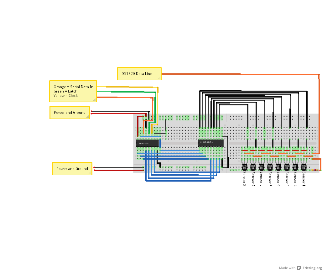
This is where i thought of the attached circuit(It may be overkill, and may be missing some componenets such as resistors etc. But that is what this thread is for).

The idea is, each sensor port has an address of its own. On initialization, the shift register is fed the relevant bits to turn on one DS1820 at a time and read the ROM code then assign that rom code to that port name.

After all 5 ports have been individually turned on, and ROM codes discovered/not found, the shift register is fed all 1's to turn all DS1820's on.

So the question:

1. What transistor should i use to switch the DS1820's on/off (or maybe even a trasistor array? i was looking at this)

2. Am i missing any resistors (maybe on the transistors or something) if so what values would you suggest.

3. Can you think of a better way to do this, other that plugging each individual sensor in to its own digital IO port on the Netduino?

4. Can you offer any modifications to make this more effecient etc...


Thanks for your help on this, Constructive critisism is appreciated and any suggestions welcome.

Regards,
Stuart.

Attached Files


#15472 DS18*20 Temperature Sensor Auto Identity Circuit

Posted by Stuart Crawshaw on 14 July 2011 - 01:01 PM in General Discussion

Another elaboration on my idea could be to sense if there is a current on a particular port. That way when you plug in a probe your code knows which socket it realtes to and can then go about checking the addresses as described above. That way it wouldn't matter which order you plugged them in you would just need a current sensing circuit across the the 5 sockets. This would work as you wouldn't simultaneously plug all 5 sensors in, so the code could easily assign the address to a variable relating to the corresponding socket that it sensed a change in current from logic level to 0.


Yes, that thought had crossed my mind, but i would like to connected/disconnect devices while the board is un-powered (to limit that chances of shorting or anything else that could happen as I am plugging the devices in.

Mainly the idea was to combat the senario what all sensors are plugged in, placed in the location to be monitored and the netduino powered on. Then i could use a menu system to say Port one is monitoring a power supply, port 2 a water filter temperature and so on, without having to connect them individually and assign their names.


#15640 Full-featured driver / test code for the Maxim DS1307 real-time clock

Posted by Stuart Crawshaw on 18 July 2011 - 03:49 PM in Project Showcase

Hi, I’m new here. I’m having a hard time trying to display time and date on a LCD.

I have wired up a Netduino, DS1307 RTC module and a 20x4 HD44780-controlled LCD on a breadboard. I can get “Hello World” to appear on the LCD, but not time and date.

Any help is welcome. Thanks in advance.


Hi,

Could you describe the problems you are having? I.E. does it just display garbage, Not at all etc...

And code examples would be a great help also.

Thanks,


#15691 Six Button Interface for LCD Menu System.

Posted by Stuart Crawshaw on 19 July 2011 - 04:47 PM in General Discussion

Back in the 90's the Parralax stamp used 1 pin for 8 switches.
Bad fritzing but will give you an idea.

In this example (cant find single pin of gnd plane :huh: )
The resistors are connected to an analoge in pin and the capacitor end is connected to gnd (or however the netduino handles it)

The whole thing reads as a potentiometer so is simple to work.
Going by what I have lurned so far you may be able to drop the cap.

I hope this helps with your button issue.


Thats an interesting idea, thank you.
Ill keep this in mind, wouldn't this idea how ever require some slight pre-programming of the values per switch and also, if i press multiple switches at once, would this not cause an issue?


#15683 Six Button Interface for LCD Menu System.

Posted by Stuart Crawshaw on 19 July 2011 - 03:10 PM in General Discussion

If you want to combine that LCD driver with other SPI devices (which is the case in my sample above) you need to use another LCDTransferProvider. I got one ready for that. Will upload it later today.


If i understand that correctly, i couldnt use the multiplexing solution as well as have an LCD on the SPI bus?

I read your post and it looks AMAZING! Just want i was looking for, but on a smaller scale :P.


#15687 Six Button Interface for LCD Menu System.

Posted by Stuart Crawshaw on 19 July 2011 - 03:34 PM in General Discussion

You will get an error because both will try to initialize the SPI bus.


The code I have would (in thory) use a centralised "shared" SPI bus (a static property of the main program, initialized on startup). Could i not modify it to work with the "shared bus"?


#15681 Six Button Interface for LCD Menu System.

Posted by Stuart Crawshaw on 19 July 2011 - 02:58 PM in General Discussion

A few months ago I published a post about multiplexing:
http://forums.netdui...h-the-netduino/

Also HD44780 LCDs can work over 74hc595 IC's.


Thanks, i shall have a read through that post,

I currently have the LCD working via a 74HC595 using the SPI bus, so its just the buttons i need to get working in a conservative fasion.

So, Ill have a read and get back to you.

Thanks again. :D


#15679 Six Button Interface for LCD Menu System.

Posted by Stuart Crawshaw on 19 July 2011 - 02:51 PM in General Discussion

Hi all,

Here is the outline,

I want to have a menu system accessible by buttons on my project. The display will be a 20x4 LCD Display and there will be 6 buttons as follows:

  • UP
  • DOWN
  • LEFT
  • RIGHT
  • OK
  • CANCEL

Now the basic idea of how these would work is have an interrupt port setup for each button (but thats 6 ports!). So now the question,

How could i achieve this, but only use the minimal number of ports?

I though about using a PISO Shift Reg, but then remembered it would need a clock etc and someway for the ND to know that data is coming in (i think).

I then there is the Matrix style setup but i would only save 1 pin (2 cols and 3 rows = 5 lines).

Any suggestions, fancy IC's or fancy components that will let be achive this goal?

Thanks for your continued support.
Stuart


#15727 I2c problems interfacing TPIC2810 Led Driver

Posted by Stuart Crawshaw on 20 July 2011 - 10:11 AM in Netduino 2 (and Netduino 1)

Hi again Matteo,

Did you try with the pull-up on the SCL line as well as the SDA?

Also,
Im not sure of the calculation needed to work out the resistor values for the pull-up resistors (sure someone could teach us both there)

But looking through the various articles it seems it can play a big part, See Here

Also, Could you advise where you attached your scope probes, just so any of these guys on here can replicate how you have your setup to see how their tests differ.

Additionally, could you explain to me the setup of your A0-A2 pins (just for my knowledge) why you set them up in such a way?
From what i can see, these would result (with the switches made) in a Logic-High? where as the address you supplied in code is all A0-2 pins being in a LOW state.

Hope we can get this resolved for you.

P.S. My old old old scope packed in last night :( so im on the lookout for a new fangled replacement and couldnt test my I2C signals as i said i would.


#15734 I2c problems interfacing TPIC2810 Led Driver

Posted by Stuart Crawshaw on 20 July 2011 - 10:48 AM in Netduino 2 (and Netduino 1)

I see, thanks for the link. But if I understand it correctly, this was supposed to reveal a possible bug (in A4/A5 multiplexing), which was not confirmed (?)


Agreed, but worth a try :)


I am in aggreement that Matteo does need a pull-up on the SCL line too...

What i am not aware of is the calculation needed to work out the value of the resistor needed, can you shed some light?


#15729 I2c problems interfacing TPIC2810 Led Driver

Posted by Stuart Crawshaw on 20 July 2011 - 10:25 AM in Netduino 2 (and Netduino 1)

[*]I don't understand exactly how instantiating and disposing OutputPort objects is supposed to 'reset' the ports, the pin is set back to input state ('floating high') when disposed. I would start with commenting this code out.[/list]

Hi CW2,

This was suggested by Chris Walker, as he advised in another post that there could be a bug in the firmware and this sometimes fixes it.

Link Here - At the bottom of post #2


#15509 Another LED "Hello world!" program

Posted by Stuart Crawshaw on 15 July 2011 - 08:48 AM in Project Showcase

Transistors are there because GPIO pins on Netduino have 8mA limit, which is not enough to power a LED.


I did not realise this, thank you for the information. Although i have plugged an LED in series with a resistor on one of the GPIO pins and it worked, Could this be drawing more current than it should?

If you light up one led at once there's no need for many resistor. When the other leds are off it's like they are disconnected from the circuit.
However, when your program wants to light 2+ leds, it's better to consider one resistor per led. (read further)


Thats what i was trying to get at, The video and description shows only one LED on at a time so i though it would be easier to use just the one resistor.

So, if you use ONE resistor for many leds, you may light more than one, but the more you light the less they shine. That's because the current is always the same and be "shared" among all the led involved in the lighting.


This in theory could make a good effect (if done quick enough) of the LED's fading in/out and the next one it lit and the other go off?


Thanks Guys and thanks for the corrections to my understanding of this circuit.


#15514 Another LED "Hello world!" program

Posted by Stuart Crawshaw on 15 July 2011 - 09:27 AM in Project Showcase

Cool, I look forward to seeing the outcome :)


#15466 Another LED "Hello world!" program

Posted by Stuart Crawshaw on 14 July 2011 - 11:39 AM in Project Showcase

Awesome, Just for my knowledge (not a critisism or anything) but could you of done this without the need for all of the transistors and resistors or was this just so you could create a circuit with an example of how a transistor could be used? Also, if the transisors were not used, could you have 1 resistor going to ground with and have that resistor as a common "gate" to ground for all of your LED's? Like i said this is not a critisism, i think your creation is an awesome little bit of electronics, im just trying to better my understanding of things (i am more of a code junkie than an electronics kinda guy). thanks,


#15410 VB2010 Express

Posted by Stuart Crawshaw on 13 July 2011 - 10:38 AM in Visual Basic Support

If I cancel the deploy and unplug the Netduino and then hit 'start debugging' while the device is booting, the code gets downloaded to the netduino without error, however, VB gets hung up. The status reports 'The debugging target is not in an initialised state; rebooting'. It hangs here and gets no further.


Hi and welcome,

I had this issues with VSCS2010, I found that if it sticks at the Debugger not initialised, simply pulling the USB and re-plugging would move things along.

Also, you stated that you could not deploy and had a communication error. Could i ask if the blue LED was constantly on at this point?

If so it may be that previous code has caused the Netduino not to boot correctly. Which would explain why rebooting it whilst trying to deploy works, as the ND does not get chance to run the existing code as new code is downloaded straight away.

I either had to do as you mentioned, or use MFDeploy to wipe the development area on the flash.

Hope this helps.

Regards,
Stuart.


#15456 VB2010 Express

Posted by Stuart Crawshaw on 14 July 2011 - 09:09 AM in Visual Basic Support

I brought my work Win7 laptop home and tried it on that and everything works fine, so I guess it's actually a WinXP issue.


If the problem is so far specific to your windows XP machine, When you plugged the device in for the first time, did you allow XP to install the driver its self or did you manually choose the driver in the SDK folders?

I had problems with the one my WinXP machine found from the internet (MS Update i think). Once i uninstalled and installed the SDK Drivers, i didnt have as many problems (the ones i was left with were silly user error type things which caused the device to need to be wiped :P )


#15693 New Soldering Iron

Posted by Stuart Crawshaw on 19 July 2011 - 05:00 PM in General Discussion

I personally use Hakko soldering equipment, and have been very happy.

They have a new entry-level soldering iron which is less than $100. I haven't used it, but if it's anything like their normal gear it's probably a solid buy.

http://www.adafruit.com/products/303

There are a ton of options out there... What does everyone else recommend?

Chris


Thanks for the suggestion Chris, not sure if these are available in the UK though, but its a good start (i could find another reputable manufacturer and look for similar if not better specs for the same price range).


#15674 New Soldering Iron

Posted by Stuart Crawshaw on 19 July 2011 - 12:27 PM in General Discussion

Hi All, Its me again :) OK, so i have finally given up on my very very cheap apparently "temperature controlled" soldering iron (its either too hot or too cold) So, as the title of this thread suggests, i am looking for a new one but on a budget. Im not looking to spend more than £100 (may be less) but want a decent solding iron with a digital display of some sort to show the current temperature... So for you standard hobbyist who will be soldering through-hole components on to vero-board such as transistors, resistors etc (none of the surface monut stuff) What would you guys suggest? What wattage is good? if 70W too low? Etc etc etc.... Thanks guys.


#15536 Pyrotechnic Sequencer

Posted by Stuart Crawshaw on 15 July 2011 - 04:22 PM in Project Showcase

I've always used Yenka (was previously called Crocodile Clips) that I still have a student licence for from school .. 10 years ago. If there's an open source sim that anyone would recommend I check out,that would be great.


Just for info, If you didnt know already, Yenka has a free license for Home users


#15478 Digital GPIO Pins Voltage

Posted by Stuart Crawshaw on 14 July 2011 - 03:55 PM in Netduino 2 (and Netduino 1)

Hey all, Just reading the specs page again, and i noticed the Digital IO pins a rated at 3.3v but are 5v tolerant. Just a simple question, will using 5v Input or Output reduce the life expectancy of the device and is using 3.3v safer/recommended over 5v? Or does it simply not matter? Thanks in advance, Stuart.


#15482 Digital GPIO Pins Voltage

Posted by Stuart Crawshaw on 14 July 2011 - 04:24 PM in Netduino 2 (and Netduino 1)

"Tolerant" means that's possible without any pain.

I'd love the humans were "tolerant" each other as the Netduino pins are with 5V.
Cheers

Great Thanks.

For the digital I/O's, it just doesn't matter. For analog I/O's it does. They are 3.3V, not 5V tolerant. An important one to keep in mind :)

Indeedy

Thank you both for your input. Just had to make sure I was doing what is recommended.


#15060 Updating Firmware Failure

Posted by Stuart Crawshaw on 05 July 2011 - 02:23 PM in Netduino 2 (and Netduino 1)

Hi Stuart Crawshaw,

Welcome to the boards!
In MFDeploy, if you click Target->Device Capabilities, what does it output?
And which firmware version did you had before, and to which version you're trying to upgrade?


Hi,

Thanks for the reply. If i run the Device Capabilities option i get:

HalSystemInfo.halVersion:               4.2.0.0
HalSystemInfo.halVendorInfo:            Netduino (v4.2.0.0 b1) by Secret Labs LLC
HalSystemInfo.oemCode:                  34
HalSystemInfo.modelCode:                177
HalSystemInfo.skuCode:                  4096
HalSystemInfo.moduleSerialNumber:       00000000000000000000000000000000
HalSystemInfo.systemSerialNumber:       0000000000000000
ClrInfo.clrVersion:                     4.2.0.0
ClrInfo.clrVendorInfo:                  Netduino (v4.2.0.0 b1) by Secret Labs LLC
ClrInfo.targetFrameworkVersion:         4.2.0.0
SolutionReleaseInfo.solutionVersion:    4.2.0.0
SolutionReleaseInfo.solutionVendorInfo: Netduino (v4.2.0.0 b1) by Secret Labs LLC
SoftwareVersion.BuildDate:              Jun  8 2011
SoftwareVersion.CompilerVersion:        400902
FloatingPoint:                          True
SourceLevelDebugging:                   True
ThreadCreateEx:                         True
LCD.Width:                              0
LCD.Height:                             0
LCD.BitsPerPixel:                       0
AppDomains:                             True
ExceptionFilters:                       True
IncrementalDeployment:                  True
SoftReboot:                             True
Profiling:                              False
ProfilingAllocations:                   False
ProfilingCalls:                         False
IsUnknown:                              False

which does seem like it has updated. But what is concerming me is that it may not be fully updated/stable as all the output from MFDeploy is not there.

I have updated from the stock FW when i bought the unit, to the 4.2 beta 1 version (including the bootloader), then tried a non-beta (4.1.0.6 i think) and that had the same output result in MFDeploy and now I have tried again with the beta (as the above output would suggest.

But as mentioned before, due to the output (or lack thereof) i am dubious as to whether it has updated correctly.


#15042 Updating Firmware Failure

Posted by Stuart Crawshaw on 05 July 2011 - 12:19 PM in Netduino 2 (and Netduino 1)

Hi All,

I am currently having a major problem updating the firmware on my netduino.

Here are the steps i am taking:

  • Open MFDEPLOY.exe
  • Click Ping (Get response "Pinging... TinyCLR")
  • Browse for update files and click Deploy
  • Progress bar says the following:
  • Connecting to device
  • Connecting to TinyBooter
  • Checking Signatures
  • Erasing 0x0010C000
  • Deploying ER_FLASH
  • Checking Signature
  • Executing Application
The progress window then closes and i am left with an output of:
Pinging... TinyCLR
Chk siCh

If i try anything else in MFDEPLOY after this, i get "Pinging... Error: No response from device"

If i disconnect it from power and then reconnect, i can then ping it but i dont think the Firmware is properly installed.

Any clues?

Thanks.


home    hardware    projects    downloads    community    where to buy    contact Copyright © 2016 Wilderness Labs Inc.  |  Legal   |   CC BY-SA
This webpage is licensed under a Creative Commons Attribution-ShareAlike License.