klotz's Content
There have been 60 items by klotz (Search limited from 08-July 24)
#10829 Keypad driver and scheme
 Posted by
on 11 March 2011 - 10:46 PM
in
Netduino 2 (and Netduino 1)
Posted by
on 11 March 2011 - 10:46 PM
in
Netduino 2 (and Netduino 1)
#2783 Stay close to your computer (or come to MakerFaire)...
Posted by
on 24 September 2010 - 05:58 PM
in
General Discussion
I noticed the spec's http://www.netduino....oplus/specs.htm say the microSD holds up to 2Gb. Is this because the Plus uses SPI to talk to the SD card or is it a software limit?Yes, and it's bedtime for sure
Chris

#9873 i2C netduino won't work!
Posted by
on 20 February 2011 - 04:13 AM
in
Netduino 2 (and Netduino 1)
#9904 i2C netduino won't work!
Posted by
on 20 February 2011 - 06:57 PM
in
Netduino 2 (and Netduino 1)
Attached Thumbnails
#9891 i2C netduino won't work!
Posted by
on 20 February 2011 - 01:01 PM
in
Netduino 2 (and Netduino 1)
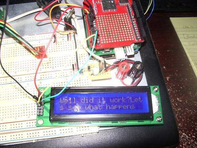
If you start from "New project" paste the embedded code to you programs.cs, you would only have to add a reference to the Newhaven Displays class.
using System;
using System.Threading;
using Microsoft.SPOT;
using Microsoft.SPOT.Hardware;
using SecretLabs.NETMF.Hardware;
using SecretLabs.NETMF.Hardware.Netduino;

namespace Netduino_With_Newhaven_Display
{
    public class Program
    {
        private static NewhavenDisplay.SerialLCD display;
        private static I2CDevice bus;

        static void sendFunction(byte[] data)
        {
            I2CDevice.I2CTransaction[] xAct = new I2CDevice.I2CTransaction[] { I2CDevice.CreateWriteTransaction(data) };
            int bytes = bus.Execute(xAct, 1000);
        }
        public static void Main()
        {
            bus = new I2CDevice(new I2CDevice.Configuration(0x50 >> 1, 100));
            display = new NewhavenDisplay.SerialLCD(sendFunction);
            display.Clear();
            display.Write("Well did it work?");
            display.Write("Lets see what happens with this one");
        }
    }
}
#2411 Buzz a piezo speaker?
Posted by
on 18 September 2010 - 04:02 AM
in
Netduino 2 (and Netduino 1)
Try
  var period = (uint)(1000000 / frequency);
  pwm.SetPulse(period, period/2);
I used the same buzzer and I just checked my code and the period is in microseconds like I remembered.
#10103 Controlling multiple LEDs with a few outputs as possible
Posted by
on 24 February 2011 - 09:34 PM
in
Netduino 2 (and Netduino 1)
First, the address should be in the range of 0x20 - 0x27. With the way it is wired, assuming the drawing is correct, the address of the configuration should be 0x20.
It appears that you have this right, but let me explain for those who may not be aware. The I2C address as used by the I2CDevice.Configuration is the 7-bit address. With some other interfaces for I2C, it is common to list two addresses for a device, one write address and one read address. The two addresses differ only in the lsb, where an even number is the write address and an odd number is the read. In the case of those interfaces, the address would be 0x40 for Write and 0x41 for Read.
This gets more confusing since some datasheets list the addresses as the Read/Write address, for instance Newhaven displays and the Sparkfun MPR121 use this method. In those cases to use the device you will often see
new I2CDevice.Configuration(ADDR >> 1, 100);
Second, according to the data sheet, when using the I2C device the speeds are 100kHz, 400kHz and 1.7 MHz so that is correct.
Now for the final point. I will admit that at this time I am just a compitent C# programmer. But I generally avoid using "var" when I know the data type. So, I would avoid using:
var setIOCON = I2CDevice.CreateWriteTransaction(new byte[] { IOCON, 0x24 });
instead I would have used:
I2CDevice.I2CTransaction setIOCON = I2CDevice.CreateWriteTransaction(new byte[] { IOCON, 0x24 });
Other than that I will see what I can do about duplicating you hardware and see if I can find something else.
#10157 Controlling multiple LEDs with a few outputs as possible
Posted by
on 25 February 2011 - 04:24 AM
in
Netduino 2 (and Netduino 1)
#929 SFE Joystick Shield
Posted by
on 20 August 2010 - 09:50 PM
in
Netduino 2 (and Netduino 1)
 .
So I added two 3 pin connectors for the servos and a LED.
Here is an update to the schematic for the shield just incase someone want to critique it.
.
So I added two 3 pin connectors for the servos and a LED.
Here is an update to the schematic for the shield just incase someone want to critique it.
Attached Files
-
 Klotz_Netduino_Servo_Joystick_Shield-V14.pdf 29.26KB
22 downloads
Klotz_Netduino_Servo_Joystick_Shield-V14.pdf 29.26KB
22 downloads
-
Joystick_Shield-v12.pdf 14.63KB
18 downloads
#912 SFE Joystick Shield
Posted by
on 20 August 2010 - 03:15 PM
in
Netduino 2 (and Netduino 1)
Personally, I like it the way it is. I was not confused by the AREF at all, my problem was that initially I did not pay attention to the fact that the shield had wired the pots to 5 vdc. Then in my haste to compensate I over drove the A/Ds by attaching AREF to 5V. Through this I learned a lot about the Netduino and its relationship to the Arduino. I won't make the same mistake again and hope that my original post will help others.The biggest reason why AREF is not connected to 3.3V internally is because the SAM7X512 chip doesn't support that natively. The AVR chip on the Arduino has an "internal AREF" as an optional integrated feature.
The other reasons we didn't just wire 3.3V to AREF and skip the AREF pin: [a] we wanted people to be aware that the Netduino was a 3.3V device and to be careful not to put 5V into the analog pins when used in analog mode; [b] we wanted to maintain the chip's capability of having an AREF which varies from 2.7V to 3.3V...for our customers who are using Netduinos for commercial engineering prototypes.
That said, I've chatted with engineering about potentially adding an "internal AREF" option in hardware on a future Netduino board revision. It would be a cool feature to have, for sure. For now, connect the AREF pin header to the 3.3V pin header with a jumper wire when using analog inputs.
Chris
I conform strongly to the concept of modularity, therefore I feel that if the shield uses A/Ds then it is responsible for supplying the AREF. It may not matter much in the case of a connected shield, but having the A/D source supply the AREF is one sure way of insuring that the A/D's are reading accurately.
So my vote would be, If you are going to add "internal AREF" it should be done via a jumper on the Netduino and the jumper should be left off by default.
I plan to make all my projects supply the AREF for accuracy, so don't break my projects please.
#878 SFE Joystick Shield
Posted by
on 20 August 2010 - 12:28 AM
in
Netduino 2 (and Netduino 1)
Attached Thumbnails

#2318 Analog Input problem
Posted by
on 14 September 2010 - 11:41 PM
in
Netduino 2 (and Netduino 1)
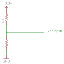
First you need to know what the resistance of the photo resister is. Mine was 25k full dark.I'm confused would it look like
AREF+3.3v->resistor(what resistance?)->ground?->photo resistor->A0?
Second you need to decide if you want it to pull-up or pull-down. I used mine in a pull-up.
Then choose a resitance to give you some kind of reasonable current limit, I chose 10K since I just wanted to play.
So using the attached schematic, I put the photoresister in a R1, a 10k in R2, you can try it either way and pick the one you like.
Attached Thumbnails
#2330 Analog Input problem
Posted by
on 15 September 2010 - 10:55 AM
in
Netduino 2 (and Netduino 1)
My guess: CadSoft Eagle (?)
Yep, I use Cadsoft Eagle. But don't ask me for help with it. I am just returning to doing hardware after 40 years and am trying to catch up.I just kindof hack away with Eagle until something works.
#2316 Analog Input problem
Posted by
on 14 September 2010 - 11:19 PM
in
Netduino 2 (and Netduino 1)
I just got my netduino and I'm starting to try to get analog input and I always get 0 when I read my pin(A0). Do you see anything I did wrong?
My setup looks like this
3.3->AREF
A0->Photo Resistor->GND
public class Program
    {
        public static void Main()
        {
            // write your code here
            InterruptPort tester = new InterruptPort(Pins.GPIO_PIN_A0, false, Port.ResistorMode.Disabled, Port.InterruptMode.InterruptEdgeBoth);
            tester.Dispose();

            AnalogInput apin0 = new AnalogInput(Pins.GPIO_PIN_A0);
            apin0.SetRange(0, 100);

            int test = 0;
            while (true)
            {
                Thread.Sleep(250);
                test = apin0.Read();
                Debug.Print("Test: " + test);
            }

        }

    }
You would need another resister to 3.3Vdc to develop a voltage divider. There is no pull-up in the An-in.
#2321 Analog Input problem
Posted by
on 15 September 2010 - 12:49 AM
in
Netduino 2 (and Netduino 1)
The fun is just beginingThank you for explaining now i understand. Time to play with my netduino!
The next thing you want to do is check out the projects page.
#6866 Question about SPI
Posted by
on 03 January 2011 - 12:25 AM
in
General Discussion
Tx and Rx are used for Asynchronous Serial communication which is sometimes described as "self clocking". This is misleading to most users in that the data rate must generally be agreed upon before hand as Chris has stated, the selfclocking come from the method for detecting the begining of the data octet or byte. Here is the Wikkipedia page that describes this http://en.wikipedia....ver/transmitter as before I can only vouch for the correctness as of Jan 2, 2010 when I read it.What are the differences between SPI and the other thing that uses TX and RX? I understand that SPI has a clock so the shift register (lets use that as an example) knows when to read the other pin for a HIGH or LOW. but then how does the TX and RX communicate? how does it know when to get the data? Are they both Serial types of communication or not? Any info is appreciated, links are good too. Thanks!
If I had a choice, I would use SPI over TX/RX because it is easier for me to use. If available and if the distance is not too great I would prefer I2C over SPI.
#6865 Question about SPI
Posted by
on 03 January 2011 - 12:19 AM
in
General Discussion
What are the differences between SPI and the other thing that uses TX and RX? I understand that SPI has a clock so the shift register (lets use that as an example) knows when to read the other pin for a HIGH or LOW. but then how does the TX and RX communicate? how does it know when to get the data? Are they both Serial types of communication or not? Any info is appreciated, links are good too. Thanks!
I don't know how much time you have to read stuff, and we could spend a lot of time asking and answering questions so I thought that it may be helpful to supply you with a link to the Wikki page that describes SPI. This may be way more than you wanted to know but there are nuances to using SPI that are not immediately apparent and which many of us take for granted. So here is the Wikki link ( and yes I read it and it is a good description on Jan 2, 2010
You know how Wikkipedia can be )http://en.wikipedia....l_Interface_Bus
#6913 Question about SPI
Posted by
on 03 January 2011 - 03:28 PM
in
General Discussion
If available and if the distance is not too great I would prefer I2C over SPI.
Could you break this down a bit more? Distance being what? If I have a central Netduino in the house, and several scattered around the property, what's the prefered for 50 -200 ft, CAT5 cable?
I would not use I2C or SPI for those distances. In the first case, one should not think of I2C or SPI as a protocol for anything say outside the box. Both are intended for communication between ICs or small peripherals, like ethernet chips, lCD displays and the like.
If I have to go more than a couple of feet, then I would start to concider one of the interconnect serial protocols like Async (TTL, RS232, or RS485.)
Then if we are in the range of Room to Room or greater I would concider ethernet.
So in answer to you direct question. At 50-200ft, especially if you have already installed CAT5, go ethernet. The shields for 'duinos are cheap and .NETMF makes it easy to program.
#6022 InterruptPort please stop interrupting me! Help.....
Posted by
on 13 December 2010 - 12:29 AM
in
General Discussion
#3239 Power Questions - i.e. Voltage
Posted by
on 30 September 2010 - 02:19 AM
in
General Discussion
I have run the Netduino, and Parallax boe bot chassis on 4 AA batterys. ( 4 x 1.5 = 6Vdc)You can step the voltage all you want, but it will come as a cost of current. 6V probably would power the Netduino, not 100% on that though, I haven't looked at the schematics yet.
I have been using the same batteries for over a week and had several test runs of the chassis. So I would say, 6VDC will just make it.
Remember you lose about 0.6-1.0 volts to a regulator and the Netduino wants a solid 3.3 Vdc for main power and 5Vdc +- 10% so your can get by.
#3596 Just cooked my 'duino
Posted by
on 07 October 2010 - 02:15 AM
in
Netduino 2 (and Netduino 1)
Hi klotz,
No fun at all. It sounds like it got fried, but you may want to try erasing the Netduino (using the ERASE) pad and seeing if you can reprogram it. It's probably fried--but there's a small possibility of recovery...
Chris
P.S. Reverse power protection and a resettable fuse are built into the Netduino. And the odd pin spacing for shields helps keep pins in the right place. But while Netduino is designed to take a certain amount of abuse, it is possible to fry a pin (or in more extreme cases, to fry a whole Netduino). Most users will be fine--but it makes me sad to see one get electrocuted...
He's dead Chris.
No amount of protection can survive an unattentive user. Just got to excited about testing my two ethernet shields and didn't notice I had plugged it in wrong. The Seeeduino shield is wider than most so it is not as easy to see the pins if you don't pick it up and inspect it.
And of course I was convince I had checked it so I let it cook while I trouble shot the failure to connect. The Atmel was way hot, and I can't get any response from it at all except a very bad smell and lots of heat.
(Kind of reminds me of like Washington D.C. or Springfield, IL)
I'll mount this one on the wall with a note "CHECK THE SHIELD" hanging from it.
That's what overconfindence will get you.
#3591 Just cooked my 'duino
Posted by
on 07 October 2010 - 12:11 AM
in
Netduino 2 (and Netduino 1)
 Well live and learn. From now on, I won't power-up without checking the connections.
Oh well now I have to order a new one
Just had to get that off my chest.
Well live and learn. From now on, I won't power-up without checking the connections.
Oh well now I have to order a new one
Just had to get that off my chest.
#3594 Just cooked my 'duino
Posted by
on 07 October 2010 - 12:39 AM
in
Netduino 2 (and Netduino 1)
I ALWAYS triple check my connections. So far, I have not fried even a single component.
I have gotten quite close thoughJust ask my temp sensor that had a backwards pinout to the dumb datasheet....
I guess I shouldn't try to work on my board with distractions. Just did not notice the pins that were not in their sockets.
#3616 Just cooked my 'duino
Posted by
on 07 October 2010 - 10:11 AM
in
Netduino 2 (and Netduino 1)
Now there's a good suggestion.Since I am normally a software guy, where would be the best place to get a replacement Atmel? Digikey is asking $20+shipping handling tax. Almost the price of a new Netduino.R.I.P.
But now you have a perfect board to practice SMD reworking (assuming you've burnt just the micro)

Any suggestion where else I should look?
#3629 Just cooked my 'duino
Posted by
on 07 October 2010 - 04:39 PM
in
Netduino 2 (and Netduino 1)
Unfortunately, the Atmel chip is about a $20 chip (of course unless it is purchased in quantity). I'd say digikey is your best bet.
Just be lucky it isn't a ~$150 chip

In either case logic dictates that I order a new Netduino. $20 + shipping and handling and frustration of removing the old and adding a new > 34.95 + shipping and handling.


