Netduino home hardware projects downloads community

Jump to content


The Netduino forums have been replaced by new forums at community.wildernesslabs.co. This site has been preserved for archival purposes only and the ability to make new accounts or posts has been turned off.

Nobby's Content

There have been 66 items by Nobby (Search limited from 01-July 23)


By content type

See this member's


Sort by                Order  

#32008 RFID Reader

Posted by Nobby on 14 July 2012 - 05:50 AM in General Discussion

Hi,

Just wondering if anyone can recommend an RFID reader that is compatible with the Netduino. I need one that can read from at least 30cm.

Can anyone help?

Thanks


I've used the Texas Instruments RFID readers in the past with AVR based projects. Unfortunately, there's no way you're going to get 30cm read range out of most units. Purely because the most available and popular units are High Frequency RFIDs(used in keycard access etc).

All the long range options are the low frequency devices(cattle tags, anti-theft etc). I can't remember off-hand what those are but the high freq devices operate at 6MHz and the low frequency devices are in the hundreds of kHz.

Either way you go, all communications are TTL/RS232 with a possible USB option.


#38804 Netduino Stops when switching relay through transistor

Posted by Nobby on 09 November 2012 - 01:03 AM in General Discussion

Hi!

Thanks for help! Finally I found the problem with Nobby's tip. I changed the base resistance from 1k to 6k and it works now in every variations. However I don't understant totally because I think that the relay's inner resistance limits the current to 70mA. So I don't know why is it a problem if the transistor's gain is too high. By the way I use a BC327-40. As I checked the datasheets its gain is above 250.

Now it works, so thank you!


Awesome work!!


250 gain is pretty high for low power circuits and 6k would be a lot better than 47k in your case. When you design in the future, transistor parameters are important. High gain will usually mean a higher forward-bias base current and larger voltage drop from base to emitter which means you'll choose a smaller base resistance etc.


As for the relay, devices like that don't have the capability to regulate/limit current unless they switch off from over-current(built in protection) so it's important to do power calculations for your transistor circuits. The current in simple circuits like this are always determined by the voltage level of your power source (i.e. 5V) and the total resistance/impedance of the circuit path the current is travelling along. If you follow those fundamental rules in design then your systems will function predictably and safely.


#38532 Netduino Stops when switching relay through transistor

Posted by Nobby on 05 November 2012 - 06:09 AM in General Discussion

As CW2 mentioned, a short could be occuring. Do you have a series resistance on the transistor collector or emitter? Another cause could be your base resistance. 1kOhm is too small. Assuming you don't use an emitter-follower BJT configuration, the base current into your BJT is 3.3V/1kOhm = 3.3mA. This current might seem small but BJTs have a current gain of at least 50 for common BJTs. When your control pin goes high, the BJT will try to draw 165mA from the 5V regulator. When you try to pull too much current from a supply, the voltage of the supply will dip and cause a reset of the Netduino. You should find out what the gain of your transistors are and calculate the base resistance to work well with your relay. For example, you need about 60mA to operate the relay and your BJT has a gain of 100. The base resistance needs to be in the ball-park figure of 55kOhms. Actual(peferred) values you can buy close to that at 56k and 47k. 56k will give you less than 60mA so I'd choose 47k in this case. For saftey, you probably have or should have a series resistor connected to the BJT collector or the emitter. If you drive a BJT hard enough, it's collector-emitter voltage can go down to 0.3V. If you don't have the series resister in there, you can virtually short the 5V rail and cause the Netduino to reset and possibly damage the board. Since your relay runs on 5V, you have to have a small series resistance so that the drop across it when you draw 60mA is small. Secondly, you don't need the anti-parallel diode since it's only for dealing with protection against negative voltages.


#39788 HTTPS support on N+2?

Posted by Nobby on 21 November 2012 - 06:41 AM in Netduino Plus 2 (and Netduino Plus 1)

I was about to start prototyping code in my existing product to use SSL for client authentication. Haven't written I line of code yet but I've read through the framework API for supported functionality. http://msdn.microsof...y/hh401316.aspx is where most of what you need can be read. I'm not sure if this component of the .Net Microframework is part of the build for Netduinos.

The basic run-down is that your device can be a client or a server as far as SSL is concerned so technically you can pull off HTTPs. If you're using basic HTTPS then you only need to store one or two certificates. One to certify your netduino as a secure server and possibly another certificate/cert chain that points to a publicly trusted certification authority(CA). If you don't care about the certificate being trusted and you just want secure communications it's pretty simple.

  • Generate and store the SSL certificate for your netduino into RAM at run-time via the CertificateStore class. Put the cert on an SD card and read it off each time you boot up
  • Use the SSLStream class for reading and writing data instead of a NetworkStream with the client socket.
  • Server authentication via the netduino certificate is mandatory but client authentication with a separate certificate is optional. Use the SSLStream.AuthenticateAsClient and AuthenticateAsServer functions.
  • Once authenticated, you use the streams like normal HTTP


#32681 Analog Pins for drive LEDs

Posted by Nobby on 26 July 2012 - 04:04 AM in Netduino Plus 2 (and Netduino Plus 1)

Hi Guys,

As I have exhausted all the Digital Pins for all my pulse counter and communication, now only left with the Analog pins untouched. May I know is there any way I can use the Analog pins for driving a LED (for machine status) purpose? also can it be configure to use to detect button press input?

Thanks in advance.


I have recently used a few of the analog pins for similar reasons as yours. I can confirm you can use them as TTL output pins and almost certainly as TTL inputs.

Just ensure the maximum forward current through each LED doesn't exceed 25mA(maximum pin current).


#32703 Release COM2 (CTS, RTS)

Posted by Nobby on 26 July 2012 - 12:58 PM in Netduino Plus 2 (and Netduino Plus 1)

Hi Nobby,

wonderful... That clears my doubts.
Just for knowledge, how can I configure PIND7 as RTS, do you have the code for it?

Thanks in advance.


Sorry I've never needed CTS or RTS in any application. I'm fairly sure its only modern use is for UART communications which have multiple devices on the shared three-wire interface and have an address they respond to. There are still some ancient RS232 devices out there which require CTS & RTS for end-to-end comms.

From what I have seen with the .Net framework though, you need to specify hardware flow control on the SerialPort object. It supports XOn/XOff and RequestToSend or a hybrid. You do this through the SerialPort.Handshake property at runtime. I believe once you configure your serial port this way, it will configure the RTS and CTS pins to function with the serial port.


#37413 PCF8574N inverted outputs?

Posted by Nobby on 19 October 2012 - 06:55 AM in General Discussion

You haven't made a mistake but have accidentally hooked it up the right way :) http://www.datasheet...o1rgkyk7ucy.pdf is the datasheet for the IC. If you go to page three you can see the circuit diagram for the output pins and the driver logic. There's two MOSFETs driving the output and they call that a totem-pole driver. With the way you've hooked it up, current flows from the 5V rail, down through the LED and resistor and then into the IC pin. The totem pole has bi-directional current flow capabilities and the current flows into the IC when the bottom MOSFET is switched on. Current flows through the MOSFET and then into GND(ground). The I/O register has an inverter which turns the MOSFET on when it's logic level is zero so that your software logic matches up with the circuit configuration. This is usually how you drive LEDs and 7 segment displays and the ICs are commonly refered to as the "sinks". Of course, you can hook it up so that current flows out of the IC, through the LED -> resistor -> GND by simply changing your circuit configuration. The switching logic levels will be opposite to how you have them already though.


#32673 Release COM2 (CTS, RTS)

Posted by Nobby on 26 July 2012 - 12:13 AM in Netduino Plus 2 (and Netduino Plus 1)

Hi Nobby,

Below is my statement.
m_objCommMgr = New cCommManager("COM2", 9600, Ports.Parity.None, 8, Ports.StopBits.One)

so far, I have not connected RTS and CTS since i am only using 3 wire interface. Since on the board layout, for COM2 it comes with RTS and CTS (derived from GPIO pins), I just wonder if we can disable these RTS and CTS when using COM2. Thus giving my project the much needed GPIO to measure the pulse input.

Care to share how do you initialise your COM2 without RTS & CTS?

Thanks in advance.


The general rule-of-thumb with microcontrollers is that pin assignments aren't always restricted to their architectural labelling. For example, a pin maybe labelled as PWM(Pulse Width Modulator) which would normally tie-in with a hardware clock and hardware interrupts. By default, the pin doesn't function as a PWM unless you actually configure it to be.

Much the same with the CTS and RTS pins, you can configure them as OutputPorts or InterruptPorts. If you try to use them for two purposes, you'll get a runtime exception when trying to initialise the pin for a second use. Example of using the RTS pin as a GPIO pin

SerialPort comPort = (SerialPorts.COM2, 9600, Parity.None, 8, StopBits.One); //Initialise COM2
OutputPort oPort = new OutputPort(Pins.GPIO_PIN_D7, false); //initialise the RTS pin as an output port with logic low as initial value;


#32649 Release COM2 (CTS, RTS)

Posted by Nobby on 25 July 2012 - 07:54 AM in Netduino Plus 2 (and Netduino Plus 1)

I have a project which utilises both UARTs and I also have RTS0 & CTS0 configured as either interupt ports or output ports with no issues. Can you please post your initialisation code for COM2?


#38173 Out of Memory - Debug.GC(true) says I'm not?!

Posted by Nobby on 29 October 2012 - 11:21 AM in Netduino Plus 2 (and Netduino Plus 1)

I haven't done an investigation yet but I had memory issues when calling three lines of StreamWriter.WriteLine(long) to save three numbers to a config file on an SD card. My netduino would report at least 21kB free mem with GC(true) then the three calls to WriteLine(long) would spew out failures to assign blocks of various sizes in the visual studio debug window before crashing from OOM exception. All I changed in the code was calling long.ToString() on all the numbers before parsing the data to the stream writer. I'm using 4.2.


#32088 Netduino Plus Socket Server Help

Posted by Nobby on 17 July 2012 - 06:16 AM in Netduino Plus 2 (and Netduino Plus 1)

TCP sockets consist of remote and local endpoints by design so naturally you'd assume the state of the connection is managed by TCP but it isn't. The only way to determine the current state of the socket is: -Enforce an activity timeout -Attempt to read from the socket -Attempt to write to the socket In the first case, simply enforce a timeout of a desired interval. If no communications occur within a certain time-frame, forcefully terminate the socket. In the second case, the operation will block indefinitely if no deterministic data stream exists(i.e. client isn't required to send data regularly). If you set a read timeout on the socket, it will throw an exception but this is a false-positive in terms of detecting a client disconnecting. The best method is to write to the socket. This is commonly refered to as Keep-Alive. If the client has closed their socket at the remote endpoint, a socket exception will be thrown at the local endpoint and you can remove the client. Send a single byte or an appropriate byte pattern to the client. They can either absorb the data or make an appropriate response if required. The problem with this approach is that the client is required at at least monitor for this incoming Keep-Alive data. End-to-End data transfer with TCP is fully-interlocked. Even if you perform a write operation on a socket asynchronously, the data backs up in the server's memory(in the netduino RAM in this case) until the client reads all pending data. This is dangerous to server stability. If you are creating an HTTP server, the HTTP specification covers the aspect of Keep-Alive and the client notifies the server through GET/POST methods whether or not they would like the connection to remain open. Even then, this is usually in the order of minutes. HTTP is typically not used for persistent connections though except in the case of data streaming. Good luck


#32654 Controlling Netduino from PC

Posted by Nobby on 25 July 2012 - 10:48 AM in General Discussion

The most common options are UART(RS232 or RS485 from the PC to the netduino) or TCP/UDP network stream/packets. The second option requires either a Netduino Plus or a Netduino with an Ethernet Shield. You can also use I2C(TWI) and SPI but you need to build interfaces at both ends. I'm not even sure you can get something like USB->TWI or USB->SPI(apart from microcontroller programmers) that you can put at the PC to send data to the Netduino. As far as I know, you can't utilise the USB socket for runtime applications but I could be wrong about that. For the 7-Seg display side of things, the serial drivers are usually the best option. They require minimal GPIO pins from the netduino compared to other options. You need to make sure the current capacity of the drivers exceeds the rating of the 7-seg displays as well otherwise they'll heat up and die fairly quickly


#31948 Any plans for have ParameterizedThreadStart available in the MF?

Posted by Nobby on 13 July 2012 - 03:41 AM in General Discussion

Good day everyone.

Any plans to have ParameterizedThreadStart available in the MF?


Thanks


You can use lambda expressions in conjunction with the standard ThreadStart class. It allows you to have type-safe targets as well.

class MyClass
{
     Thread myThread = null;

     public MyClass()
     {
         this.myThread = new Thread(() => MyClass.threadFunc(this));
         this.myThread.Start();
     }

     private static void threadFunc(MyClass myClassObject)
     {
            //do stuff here
     }
}

Target delegate doesn't have to be static either


#33833 .NET Micro Framework 4.3 Roadmap

Posted by Nobby on 17 August 2012 - 03:33 PM in General Discussion

I recently moved to 4.2 RTM to take advantage of the reduced networking byte-code size which I read about in a forum post on here somewhere. Where does general information about new microframework footprint sizes come from?


#39296 Connecting a motor to the netduino

Posted by Nobby on 13 November 2012 - 10:19 PM in General Discussion

You've got two goals to achieve here. Your circuit build/hook-up and software to control the H-Bridge. The good news is that regardless of how you end up controlling the H-Bridge, the connections are the same.


You haven't specified what your H-Bridge is and how it's been put together etc. They're simple systems to understand. You need to connect at least three different kinds of connections:


  • DC Bus link voltage. This is the power supply you provide the H-Bridge. It can be bi-polar or uni-polar but it depends on if your H-bridge will allow you to connect a 'center-tap' for setting the ground as a mid-point.
  • CMOS/IGBT gate inputs. You connect your PWM outputs to these. There are four of them but they are in pairs so you only need two PWMs to drive it. One switch is always off when the other is on for each pair(side note on this)
  • H-Bridge output goes to the motor. You will be able to drive a DC or an AC motor with an H-bridge.

There may be some other component considerations depending on the gear you've bought.

Controlling the motor can be as easy or difficult as you want and it's a massive field for you to explore. To start with, you will most likely be able to get a library or use .Net classes which will operate the PWMs for you. Because you have an H-Bridge you have two options:


  • Use one PWM on half of the H-Bridge as a starting point. It turns your H-Bridge into a single phase-leg modulator which means you can't drive an AC motor
  • Use two PWMs on the full H-bridge which will allow you to drive an AC motor as well as DC

Above is your starting point but it has no feedback control loop. Without feedback from the motor, you won't be able to know how fast it is actually spinning for a given input signal. If it's important for you to have precise control of the motor speed, you need software in your project which will measure the motor speed and figure out the difference in desired speed and actual speed the adjust your modulation depth to drive the H-bridge harder or less. Some motors can tell you their position as well so you can precisely control the position of the motor as well as speed.

Having said all this, if you're just a hobbyist and want to see the motor spin, you don't need a feedback control system or understand much about modulation theory. If you told us more about your goals then we can be very specific about helping you to setup the right system.


--edit: oops forgot the side note. Depending on how your H-bridge has been designed, you have to build a "dead-zone" into the PWM signal. If there's free-wheeling diodes and/or your H-bridge uses IGBTs, there's a discharge transient when the device attempts to switch off. If you toggle the other switch on before its complimentry switch has fully turned off, you create a short on your power supply every time the PWM switches on/off. It will damage your supply and possibly much more.


#31951 Timing Accuracy Issues

Posted by Nobby on 13 July 2012 - 03:54 AM in General Discussion

I'm currently looking into factors affecting the accuracy of Netduino timing. Precision isn't a massive factor, tenths of a second is fine. I've tried two approaches for timing -Using a timer interrupt with constant frequency/Thread.Sleep and then making timing variable adjustments -Implementing Chris Walker's System::Diagnostics::StopWatch and using ElapsedMilliseconds The first approach is the easiest but overhead causes loss in accuracy. The second approach would have the higher accuracy but has a dependency on the framework runtime overhead. System::TimeSpan::TicksPerMillisecond is also fixed at 10,000 instead of being device specific. At the moment, I'm curious as to what factors cause the runtime DateTime clock to slip. I have an application with various medium performance threads running, one being a timing thread. Over a space of 15mins, the timer has fallen more than 10 seconds behind my sports watch and a synchronised timer on a PC application I have running. The Netduino is not being debugged, has release build code deployed to the target board and is broadcasting its time through UART to be observed. Considering the crystal freq of the Netduino Plus, I'm unsure as to the massive accuracy/overhead issues with timing here. I'm currently using the 4.2 framework and firmware associated with that framework.


#31955 Timing Accuracy Issues

Posted by Nobby on 13 July 2012 - 05:19 AM in General Discussion

Another observation I have made recently in the Netduino plus was similar to this issue. It was before I had upgraded the firmware so it was still running 2.1.xxxxx and .Net Framework 4.1. I had a TTL VGA board and I was displaying the value of DateTime.Now on a screen directly from the Netduino through COM1. On startup, the Netduino would perform a one-time synchronisation of Date & Time from my PC with the help of an application I had wrote to communicate with the Netduino. It had millisecond percision. After about 5 minutes or so, I noticed that DateTime.Now had lagged behind my PC by a few seconds. After leaving it there idle for nearly a day, it was a long way behind. Initially I beleived the discrepency to be with flucutations of time data when my PC was synchronising with my Domain Controller time server until I disabled time synchronisation on my PC and had the same result as well as using my stopwatch as a reference. I'm about to try this project on a standard Netduino running 2.1.xxxx


#31958 Timing Accuracy Issues

Posted by Nobby on 13 July 2012 - 05:31 AM in General Discussion

Hey Nobby,

Thank you for the additional information. Let's boil it down a bit more, to isolate any potential code or threading issues...

Can you please try creating an app which simply does the following:

  • Create and open an instance of the SerialPort class
  • In a loop: write the current time to the serial port and then sleep 500ms

And then share that code along with your results? If that basic case is losing 1+ seconds per minute...or if it's not...then we'll have a good basis for diagnostics.

Thank you, Nobby.

Chris


Getting onto that right now.


#31953 Timing Accuracy Issues

Posted by Nobby on 13 July 2012 - 05:01 AM in General Discussion

Hi Nobby,

Is the elapsed time from timers/Stopwatch not matching the increase in DateTime.Now?

Losing 10 seconds in 15 minutes is a lot (~1.1%).

Can you post a quick code snippet showing how you're calculating and writing out the time? We should be able to run it on our Netduinos to reproduce...

Finally...just curious: if you reflash the mainboard with Netduino firmware (instead of Netduino Plus) do you get the same results?

Chris


Hey Chris,

Due to the nature of my project, I can't share code but I have created a new project which is dedicated to the task of timing using Ticks.

The project has three threads. The main program thread, aka Main(), sits in a for(;;) 
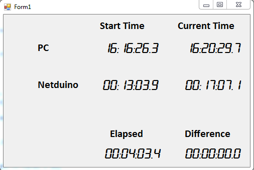
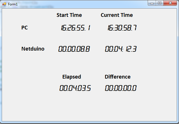
loop with a Thread.Sleep(500) call. It does this after it initialises a class that manages the time measurements.

The second thread is fed a time object and reduces its time until it reaches zero or less. The thread is executed with default priority through a lambda expression.

 private static void timerFunc(Clock clock)
        {
            if (clock == null) return;

            long startTicks = Microsoft.SPOT.Hardware.Utility.GetMachineTime().Ticks;
            long endTicks, delta;
            while (clock.time > 0)
            {
                endTicks = Microsoft.SPOT.Hardware.Utility.GetMachineTime().Ticks;
                delta = (endTicks - startTicks) / m_tick; //where m_tick is System.TimeStamp.TicksPerMillisecond

                clock.time -= delta;

                startTicks = Microsoft.SPOT.Hardware.Utility.GetMachineTime().Ticks;
                Thread.Sleep(50);
            }            
        }

The third thread is one that runs in the clock class. It sleeps for 100ms and then uses COM1 to write, in ASCII text, the value of the time of the format "mm:ss.f".

I just started a 15min test against my sports wristwatch and PC application. 10mins into the test, clock.time is eight seconds higher than the timer on my watch.

I haven't tried flashing my Netduino Plus with the Netduino firmware. I have a regular Netduino to use and a handfull of Netduino Plus devices I can downgrade if necessary.

Currently, I'm stuck with the newest firmware for my commercial project. Purely because of the Socket runtime code footprint providing a much needed 10K.

Thanks for having a look at this


#31963 Timing Accuracy Issues

Posted by Nobby on 13 July 2012 - 07:50 AM in General Discussion

I setup and experiment that follows the guidelines you provided. I created a simple PC app to track any time slip over an elapsed time. Each experiment itteration was roughly 4 mins long. Attached are images showing the differences between different timing strategies.

-mainThread.png shows your experiment rules. Over four mins, there is no clock drift between PC and Netduino DateTime.Now

-threadedMachineTime.png shows the same experiment except data transmission is done every 100ms on one thread and the current machine time is stored in clock.time on another thread every 50ms. There is no drift apart from 100ms synchronisation conflicts between threads every now and then which go back to zero anyway.

-stopwatch.png System.Diagnostics.StopWatch approach shows a drift of about 200ms every two minutes. Clock.time is incremented by stop_ticks - start_ticks after a thread.sleep(50). The itterative code is shown below. It should essentially always match the netduino machine time. There is only 1 line of code overhead separating

for(;;)
{                
                endTicks = Microsoft.SPOT.Hardware.Utility.GetMachineTime().Ticks;
                delta = endTicks - startTicks;
                startTicks = Microsoft.SPOT.Hardware.Utility.GetMachineTime().Ticks;

                clock.time += delta;  
                //clock.time = Microsoft.SPOT.Hardware.Utility.GetMachineTime().Ticks; //this was used in the second experiment
                Thread.Sleep(50);
}   

-internalDrift.png shows how clock.time drifts away from the Netduino system time. The netduino experiment code was modified to only transmit the drift between Microsoft.SPOT.Hardware.Utility.GetMachineTime().Ticks and clock.time(shown in the Current Column for Netduino). The results show that the Netduino clock doesn't drift compared to the PC clock rather clock.time is drifting behind the Netduino clock. As you can see from the code above though, there's nothing to it. Certainly no reason for such a rediculous lack of accuracy. Even if I changed the code so that start_ticks = end_ticks after calculating delta, it doesn't make much of a difference. I did notice that if I reduce or increase the sleep time from 50 down to 25 or up to 100, the accuracy of timing was affected but minimally.

What can you tell me about operations and overhead with large datatypes such as System.Long? Could it be significant?

I will restructure this experiment to perform stopwatch-based approach in the main thread and see what results I get.

Attached Thumbnails

  • mainThread.PNG
  • stopwatch.png
  • threadedMachineTime.PNG
  • internalDrift.PNG


#32508 Microsecond timing

Posted by Nobby on 23 July 2012 - 07:59 AM in Netduino Plus 2 (and Netduino Plus 1)

Microsoft.SPOT.Hardware.Utility.GetMachineTime().Ticks has 100ns precision(0.1us) but the accuracy is skewed by +- a few hundred microseconds due to the runtime overhead. If you need to measure an interval less than one millisecond, you end up with an error of about 20% but this error is negligable for slightly larger intervals. The 100ns precision is definitely usefull for cumulative timing functionality. Are you using the timer as a measurement interrupt?


#32581 Passing Servo's to another thread.

Posted by Nobby on 24 July 2012 - 12:03 AM in Netduino Plus 2 (and Netduino Plus 1)

There's two ways you can do this. -As linked by Hanzibal, you can use lambda expressions to parse the Servo objects to a function as a parameter when creating the thread. -Create a class which encapsulates the Servo objects as members. You can create regular threads for each servo and address the servo objects as this.servo1 and this.servo2. Your example code executes within a static function so it's not possible to use servo objects initialised in that function unless they are parsed to another static function or class method as parameters. Using option two makes it easier to manage your objects and use them across threads.


#32011 Timing Accuracy Issues

Posted by Nobby on 14 July 2012 - 08:44 AM in General Discussion

The final observation I made with time slip came down to precision rather than accuracy. Initially my timing precision was in milliseconds. Naturally I elected to just utilise TimeSpan.Ticks/TicksPerMillisecond. The major issue with cumulative timing measurements here is a significant degree of time slip due to rounding-down. The slip increases as the sampling frequency increases. An example of slip due to measurement error was about 100ms every four mins for a interval measurement frequency of 20Hz. I still only require millisecond precision but now use 100 nanosecond precision for higher frequency timing intervals.


#31973 Timing Accuracy Issues

Posted by Nobby on 13 July 2012 - 12:41 PM in General Discussion

I've nailed the culprit on this one but no explaination as to the adverse result obtained. Take the code snipet below:

            long startTicks = Microsoft.SPOT.Hardware.Utility.GetMachineTime().Ticks, endTicks=0, delta=0;                        
            int sleepTime = 50, choice=1;
            
            clock.start = startTicks;

            for(;;)
            {
                if (choice == 0)
                {
                    Thread.Sleep(sleepTime); //Sleep to regulate timing intervals. 50ms here.

                    endTicks = Utility.GetMachineTime().Ticks; //Get the current Netduino time
                    delta = endTicks - startTicks; //Calculate the time difference
                    startTicks = endTicks; //Assume significant overhead from the previous line of code

                    clock.time += delta; //Increment instance member time value
                }
                else if (choice == 1)
                {
                    Thread.Sleep(sleepTime);

                    endTicks = Microsoft.SPOT.Hardware.Utility.GetMachineTime().Ticks;
                    delta = endTicks - startTicks;
                    startTicks = Utility.GetMachineTime().Ticks; //Assume no overhead from the previous line of code and this line as well

                    clock.time += delta;
                }
                else if (choice == 2)
                {
                    //Choices 2 & 3 just involve a different order of operations but have the same logic as 1 & 2
                    endTicks = Utility.GetMachineTime().Ticks;
                    delta = endTicks - startTicks;                    
                    startTicks = endTicks; //Assume overhead from the previous line of code

                    clock.time += delta;

                    Thread.Sleep(sleepTime);
                }
                else if (choice == 3)
                {
                    endTicks = Utility.GetMachineTime().Ticks;
                    delta = endTicks - startTicks;
                    startTicks = Utility.GetMachineTime().Ticks; //Assume no overhead from last and this line of code

                    clock.time += delta;

                    Thread.Sleep(sleepTime);
                }
            }

I performed some optimisations on my original timing code which was not optimised at the time. There was still drift. The results were fairly conclussive though. Choices 0 & 2 provided identical and ideal results. There was no slip between clock.time, the Netduino time and the PC time.

Choices 1 & 3 resulted in the slip of 100ms every 30seconds. The only difference in code was using startTicks = Utility.GetMachineTime().Ticks vs startTicks = endTicks. The previous line of code, delta = endTick - startTicks and the alternative code in choices 1 & 3 were resulting in what appears to be significant overhead. Based on the results and a loop interval of roughly 50ms, it works out to be roughly 166us of slip per itteration.

Not being a huge fanatic of investigating the inner workings of the micro framework, I'm just going to accept that I can't be lazy in design with respect to these things. Failing longer duration tests for choices 0 & 2, There's no evidence of any chronic issue with timing accuracy.


#32848 ADC

Posted by Nobby on 28 July 2012 - 01:33 PM in Netduino Plus 2 (and Netduino Plus 1)

Thank you Mario for your response.

I know that the framework slows things down..But most of teh time the developper is the problem!

But I know that on a PC, the differences is sometimes hard to see..
The conversion time of an ADC can be less than 5 Microseconds..
A simple loop with simple calculation run very fast.
It is the call to the ADC which goes wrong.
Usually, it is possible to start conversion, than to read the result later.
With NetDuino, it seems that we have to start and wait conversion..
Even though, response time is very long...

What I want to to is to store data from 1khz ->10khz signal into memory, and dump it from a PC.
It works fine for 100hz signal..


I will work on it...


If you configure the ADC to operate in free-running mode, the contents of the ADC register is constantly changing for you at the maximum rate the ADC will operate at. This kinda eliminates conversion times from a hardware interrupt. There are two probelms with a free-running ADC.

If you strobe multiple pins you run into parallel operation errors. I haven't checked the SAM7 architecture but most AVRs only have 1 ADC but have 5+ pins you can strobe off. When you change the ADC strobing register to select another pin, it might be impossible to determine which pin the ADC data register contents belongs to if you read it immediately or shortly after. Some AVRs don't allow free-running with strobing.

The other issue you have is when you read a sample from the ADC register in free-running mode, you don't know how "old" the data is. When you take two readings, there will always be a degree of skew in your measurement windows which increases with a slower ADC sampling rate.

Those two issues aside, it's also a tall-order to measure a time interval less than 1ms accurately.


home    hardware    projects    downloads    community    where to buy    contact Copyright © 2016 Wilderness Labs Inc.  |  Legal   |   CC BY-SA
This webpage is licensed under a Creative Commons Attribution-ShareAlike License.