

 Find content
 Not Telling
        public static void Main()
        {

            SPI.Configuration Device1 = new SPI.Configuration(
            Pins.GPIO_PIN_D10, // SS-pin
            false,             // SS-pin active state
            0,                 // The setup time for the SS port
            0,                 // The hold time for the SS port
            true,              // The idle state of the clock
            true,             // The sampling clock edge
            1000,              // The SPI clock rate in KHz
            SPI_Devices.SPI1   // The used SPI bus (refers to a MOSI MISO and SCLK pinset)
            );
            SPI SPIBus = new SPI(Device1);

            while (true)
            {
                byte[] WriteBuffer = new byte[2];
                WriteBuffer[0] = 0;
                WriteBuffer[1] = 0;
                SPIBus.Write(WriteBuffer);
                WriteBuffer[0] = 16;
                WriteBuffer[1] = 0;
                SPIBus.Write(WriteBuffer);
                Thread.Sleep(1000);
                WriteBuffer[0] = 0;
                WriteBuffer[1] = 127;
                SPIBus.Write(WriteBuffer);
                WriteBuffer[0] = 16;
                WriteBuffer[1] = 127;
                SPIBus.Write(WriteBuffer);
                Thread.Sleep(1000);
            }
        }
Posts I've Made
In Topic: SPI and digital potentiometer (MCP4231)
09 February 2012 - 04:35 PM
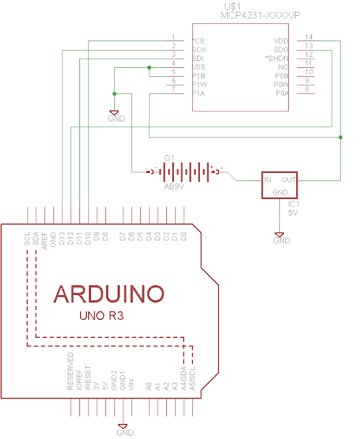
I'm pretty sure it's wired correct, but I have included a schematic of how everything is connected. You'll have to forgive the crudeness I'm still learning Eagle. I should also mention that I'm using a separate power source and 5V voltage regulator. When I measure the voltage between P1W and P1B I'm getting ~2.46 which is what I would expect from the 4.93V from the regulator.
The wires I am using are about 4 inches. I will try shortening the SPI connections a bit.
I do not have an oscilloscope but I'm assuming if I'm going to keep this up it would be a good investment. Any suggestions on a scope that would be good for a novice such as myself that wont completely drain the bank?
Thanks!
In Topic: SPI and digital potentiometer (MCP4231)
09 February 2012 - 01:43 PM
Ok, I changed those values (I should have read the wiki a little better  ) and I'm still not getting anything. I have everything setup in a breadboard but I didn't add the decoupling capacitors to my circuit. At my current clock speed is that going to be a problem? Thanks!
) and I'm still not getting anything. I have everything setup in a breadboard but I didn't add the decoupling capacitors to my circuit. At my current clock speed is that going to be a problem? Thanks!


