Netduino home hardware projects downloads community

Jump to content


The Netduino forums have been replaced by new forums at community.wildernesslabs.co. This site has been preserved for archival purposes only and the ability to make new accounts or posts has been turned off.
Photo

SPI and digital potentiometer (MCP4231)


  • Please log in to reply
7 replies to this topic

#1 itsme

itsme

    New Member

  • Members
  • Pip
  • 6 posts

Posted 09 February 2012 - 12:30 AM

First I would like to say in the month I have had my netduino I have learn a ton. These things rock.

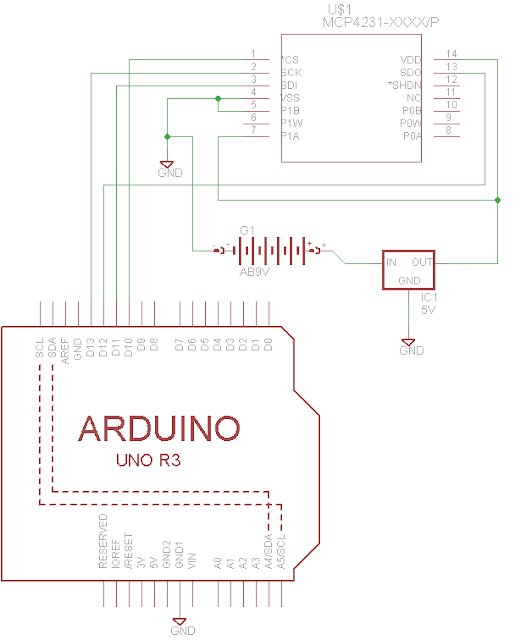
Ok to my question. I am trying my hand at running a digital potentiometer(Specifically a MCP4231). I would like to use it as a variable voltage divider to mimic/replace a joystick from an electric wheel chair. So I've read through the datasheet and while I'm pretty sure that I understand how to connect it, I'm not sure that I have the SPI object initialized correctly, or if I do have it initialized correctly, if i am sending the correct commands. Any light shed will be greatly appreciated. Thanks!

Here is my code. Almost verbatim from the wiki.

        public static void Main()
        {

            SPI.Configuration Device1 = new SPI.Configuration(
            Pins.GPIO_PIN_D10, // SS-pin
            true,             // SS-pin active state
            0,                 // The setup time for the SS port
            0,                 // The hold time for the SS port
            false,              // The idle state of the clock
            true,             // The sampling clock edge
            1000,              // The SPI clock rate in KHz
            SPI_Devices.SPI1   // The used SPI bus (refers to a MOSI MISO and SCLK pinset)
            );
            SPI SPIBus = new SPI(Device1); 

            while (true)
            {
                // Writes a single byte with value 255 to the SPI device
                byte[] WriteBuffer = new byte[2];
                WriteBuffer[0] = 0;
                WriteBuffer[1] = 0;
                SPIBus.Write(WriteBuffer);
                Thread.Sleep(1000);
                WriteBuffer[0] = 0;
                WriteBuffer[1] = 120;
                SPIBus.Write(WriteBuffer);
                Thread.Sleep(1000);
            }
        }


#2 Mario Vernari

Mario Vernari

    Advanced Member

  • Members
  • PipPipPip
  • 1768 posts
  • LocationVenezia, Italia

Posted 09 February 2012 - 09:03 AM

Hello "itsme" and welcome to the forum.

There are acouple of errors in the SPI configuration:
  • according to the datasheet, the active level for the chip-select (CS) is "LOW", thus the "SS-pin active state" must be "false";
  • again, the idle state of the clock should be high, thus "true".
You can check these parameters at page 11 (fig 1.1) of the datasheet.

Hope it helps.
Cheers
Biggest fault of Netduino? It runs by electricity.

#3 itsme

itsme

    New Member

  • Members
  • Pip
  • 6 posts

Posted 09 February 2012 - 01:43 PM

Ok, I changed those values (I should have read the wiki a little better :) ) and I'm still not getting anything. I have everything setup in a breadboard but I didn't add the decoupling capacitors to my circuit. At my current clock speed is that going to be a problem? Thanks!

#4 Mario Vernari

Mario Vernari

    Advanced Member

  • Members
  • PipPipPip
  • 1768 posts
  • LocationVenezia, Italia

Posted 09 February 2012 - 02:48 PM

Well, I watched the datasheet quickly, and I didn't realize that the chip supports both the idle clock high and low. Okay, never mind. It should work anyway. Decoupling caps are a good practice, but I won't point on this missing the not-working of the circuit. Instead, I'd check the wiring once again (although I'm sure you done it), and take care to keep the wiring short as possible. I keep the SPI wiring 5-10 cm at most (2-4 in). Finally, "no": 1 MHz is not a problematic frequency, unless the wiring is short enough. I assume you don't have a scope...it would be useful.
Biggest fault of Netduino? It runs by electricity.

#5 itsme

itsme

    New Member

  • Members
  • Pip
  • 6 posts

Posted 09 February 2012 - 04:35 PM

I'm pretty sure it's wired correct, but I have included a schematic of how everything is connected. You'll have to forgive the crudeness I'm still learning Eagle. I should also mention that I'm using a separate power source and 5V voltage regulator. When I measure the voltage between P1W and P1B I'm getting ~2.46 which is what I would expect from the 4.93V from the regulator.
Posted Image

The wires I am using are about 4 inches. I will try shortening the SPI connections a bit.

I do not have an oscilloscope but I'm assuming if I'm going to keep this up it would be a good investment. Any suggestions on a scope that would be good for a novice such as myself that wont completely drain the bank?

Thanks!

#6 Mario Vernari

Mario Vernari

    Advanced Member

  • Members
  • PipPipPip
  • 1768 posts
  • LocationVenezia, Italia

Posted 09 February 2012 - 06:33 PM

Sorry for the delay: I was commuting from office to home.
That sounds like a puzzle. The circuit is okay, everything looks correctly wired.
The only clue I'd have is on the /SHDN input left open: just try to wire it to +5V. Almost sure that's no solving the problem, but...

Well, another clue!
The command you are sending is targeting the POT #0, but you're actually measuring POT #1. Please, check the command, or move the wiring.

About scopes...there's an old discussion about this argument, because many users were asking (still now) about scopes.
Read these:
http://forums.netdui...-with-netduino/
http://forums.netdui...-oscilloscopes/

I own a UNI-T 100MHz, with logic analyzer. I know that many users recommend Rigol. Also Atten is pretty good.
Avoid DSO-Nano: I owned, but it's much like a toy.

You looks pretty skilled on electronics, thus I'd suggest a good scope: 50-60MHz at least, two traces, logic analyzer is a plus. If you like playing with circuits, skip a simple Logic Analyzer, and choose a scope.
Cheers
Biggest fault of Netduino? It runs by electricity.

#7 itsme

itsme

    New Member

  • Members
  • Pip
  • 6 posts

Posted 09 February 2012 - 07:35 PM

Oops! Wow well looks like assumptions are still a bad idea. I switched the wires over to the actual channel 0 and BAM beautiful 0V-5V variations.Thanks a ton!

#8 itsme

itsme

    New Member

  • Members
  • Pip
  • 6 posts

Posted 10 February 2012 - 05:11 AM

Just thought it would be worth noting since it wasn't obvious to me. Accessing the second channel is done by the setting the first byte in the array to 16 (0001 0000). See page 48 of the data sheet Volatile Wiper 1 Write Data. I also included the sample code I got to work. Maybe that will help someone in the future.
        public static void Main()
        {

            SPI.Configuration Device1 = new SPI.Configuration(
            Pins.GPIO_PIN_D10, // SS-pin
            false,             // SS-pin active state
            0,                 // The setup time for the SS port
            0,                 // The hold time for the SS port
            true,              // The idle state of the clock
            true,             // The sampling clock edge
            1000,              // The SPI clock rate in KHz
            SPI_Devices.SPI1   // The used SPI bus (refers to a MOSI MISO and SCLK pinset)
            );
            SPI SPIBus = new SPI(Device1);
                        
            while (true)
            {                
                byte[] WriteBuffer = new byte[2];
                WriteBuffer[0] = 0;
                WriteBuffer[1] = 0;
                SPIBus.Write(WriteBuffer);                
                WriteBuffer[0] = 16;
                WriteBuffer[1] = 0;
                SPIBus.Write(WriteBuffer);
                Thread.Sleep(1000);
                WriteBuffer[0] = 0;
                WriteBuffer[1] = 127;
                SPIBus.Write(WriteBuffer);
                WriteBuffer[0] = 16;
                WriteBuffer[1] = 127;
                SPIBus.Write(WriteBuffer);
                Thread.Sleep(1000);
            }
        }


0 user(s) are reading this topic

0 members, 0 guests, 0 anonymous users

home    hardware    projects    downloads    community    where to buy    contact Copyright © 2016 Wilderness Labs Inc.  |  Legal   |   CC BY-SA
This webpage is licensed under a Creative Commons Attribution-ShareAlike License.