Mike P's Content
There have been 41 items by Mike P (Search limited from 03-July 24)
#17499 Wiki tutorial on SPI
 Posted by
on 04 September 2011 - 01:37 AM
in
General Discussion
Posted by
on 04 September 2011 - 01:37 AM
in
General Discussion
#17521 Wiki tutorial on SPI
Posted by
on 04 September 2011 - 12:31 PM
in
General Discussion
#17966 Where is DateTime?
Posted by
on 14 September 2011 - 04:12 AM
in
General Discussion
http://forums.netdui...uino-date-time/
#17567 What is this called?
Posted by
on 05 September 2011 - 09:17 AM
in
General Discussion
#17702 What is this called?
Posted by
on 07 September 2011 - 01:42 AM
in
General Discussion
The decoupling cap serves to smooth out the power supply. It acts like a shock absorber on the supply voltage. Without it small spikes on the power supply would be created whenever loads were switched on and off and these spikes might be transfered to the output signal.
The spikes on the output could be mistaken for real output transitions and cause the encoder to lose its count.
I posted some code on the Wiki last night for a rotary encoder. Chances are that it would work fine with your strip as well.
http://wiki.netduino...oder-Input.ashx
#17286 Unable to deploy without disconnect\reconnect USB cable
Posted by
on 30 August 2011 - 09:47 PM
in
Netduino Plus 2 (and Netduino Plus 1)
#15914 Unable to deploy without disconnect\reconnect USB cable
Posted by
on 26 July 2011 - 10:00 AM
in
Netduino Plus 2 (and Netduino Plus 1)
#19481 SPI, Netduino, and RGB LED Strip
Posted by
on 21 October 2011 - 12:56 AM
in
General Discussion
#19465 SPI, Netduino, and RGB LED Strip
Posted by
on 20 October 2011 - 06:17 PM
in
General Discussion
Let's remove all the other code from the list of suspects and focus on just getting the SPI transfer functional.
This should set the first 3 LEDs to Red, Green, Blue.
        public static void Main()
        {
            byte[] buffer = new byte[] { 0xFF,0x00, 0x00,  0x00,0xFF,0x00, 0x00,0x00,0xFF };
            SPI.Configuration xSPIConfig;
            SPI xspi;
            xSPIConfig = new SPI.Configuration(Pins.GPIO_NONE, false, 0, 0, false, true, 100, SPI.SPI_module.SPI1);
            xspi = new SPI(xSPIConfig);
            while (true)
            {
                xspi.Write(buffer);
                Thread.Sleep(100);
            }
        }
#19568 SPI, Netduino, and RGB LED Strip
Posted by
on 21 October 2011 - 10:02 PM
in
General Discussion
#19565 SPI, Netduino, and RGB LED Strip
Posted by
on 21 October 2011 - 09:08 PM
in
General Discussion
#19429 SPI, Netduino, and RGB LED Strip
Posted by
on 20 October 2011 - 10:45 AM
in
General Discussion
The bug Mario refers to would only affect you if you used clock_idle=true. This is because the SPI firmware always sets clock to false after the transaction.
The bug has no effect if using clock_idle=false.
The WS2801 spec says it's good for up to 25MHz clock speed. Don't try to set 25MHz though because you will end up with 48MHz. You should be able to use 24MHz though if you keep lead length short. But there's no reason that 2MHz shouldn't work.
You could try running the strip at Vcc=4V or less. Add a couple of 1N4007 diodes in series to drop the voltage. The chip is spec'd for 3.3-5V VCC but obviously the LED intensity would be lower. This would only be to prove that the logic hi level is not the issue.
For those reading this thread who haven't looked at the data sheet the specification for a logical high input level is 0.8* Vcc. With Vcc at 5v this means a minimum voltage of 4v is required to be certain it is registered as logic hi. Netduino can only put out 3.3v on the outputs.
Since your chip does not use the CS, you should use CS = GPIO_None. Pin 13 on the mini is the only pin that you can't use for CS (with the currently released firmware) the same is true for Pin 4 on the netduino(&plus)
This is due to some functionality in the .NETMF porting kit that was abandoned but not completely removed.
I can't see how this could stop your code from working though.
Are you using the latest firmware? 4.1.0.6 or 4.2?
If I were you, I would buy myself an Open bench logic sniffer from Seeed studios. It'll be the best $50 you've ever spent.
A logic shrimp or a bus pirate might even be sufficient. Or borrow an oscilloscope from someone.
I duplicated Stefan W's sample on my Netduino plus (FW4.1.0.6) and got a different result.
Here is my sample taken using the Logic Sniffer
        public static void Main()
        {
            byte[] buffer = new byte[] { 0x55, 0xFF, 0X00, 0X55, 0XAA };
            SPI.Configuration xSPIConfig;
            SPI xspi;
            xSPIConfig = new SPI.Configuration(Pins.GPIO_NONE, false, 0, 0, false, true, 100, SPI.SPI_module.SPI1);
            xspi = new SPI(xSPIConfig);
            while (true)
            {
                xspi.Write(buffer);
                Thread.Sleep(100);
            }
        }
Even at 100kHz there is nothing like a 500us break in the transmission. The GC (garbage collector) may run between bytes during an SPI write comman making a slightly longer delay between bytes but it would never get to anything like 500us.
#19513 SPI, Netduino, and RGB LED Strip
Posted by
on 21 October 2011 - 09:38 AM
in
General Discussion
#19463 SPI, Netduino, and RGB LED Strip
Posted by
on 20 October 2011 - 06:07 PM
in
General Discussion
#19502 SPI, Netduino, and RGB LED Strip
Posted by
on 21 October 2011 - 07:28 AM
in
General Discussion
#17750 SPI bug report (NETMF bug)
Posted by
on 08 September 2011 - 11:40 AM
in
Beta Firmware and Drivers
Feel free to visit codeplex and vote.
http://netmf.codeple...m/workitem/1219
AT91_SPI_Driver::Xaction_Stop() has CS release sequence reversed
After the SPI transaction completes the Chip Select should be released before setting MOSI, MISO and SCLK to their idle levels.
in 4.1 and 4.2RC2 the MOSI and SCLK pins are both set low before CS is deactivated.
I am not sure but perhaps SCLK should be set low or high to honour the Clock_IdleState setting.
The file is C:\MicroFrameworkPK_v4_2\DeviceCode\Targets\Native\AT91\DeviceCode\AT91_SPI\AT91__SPI.cpp
Lines 376-384 should be moved up to line 342
This would only cause a problem for slaves where the Clock_IdleState was true. In this instance an unwanted clock edge is sent before chip select is released. Depending on how the slave has been implemented this may have no effect.
Here is a capture of the SPI transfer and you can see MOSI and SCLK being set low before CS is released.traces are SCLK, MOSI, MISO, CS.
#17235 Six Button Interface for LCD Menu System.
Posted by
on 29 August 2011 - 01:37 PM
in
General Discussion
#17279 Six Button Interface for LCD Menu System.
Posted by
on 30 August 2011 - 04:12 PM
in
General Discussion

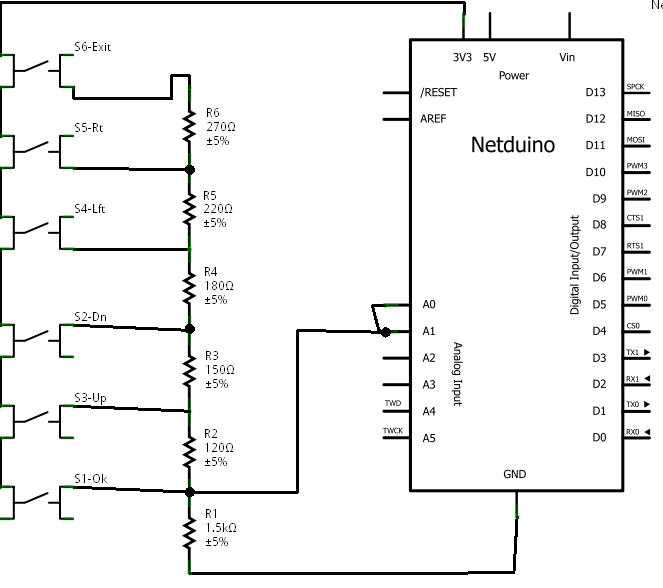 I tried to put a table in below but the TABs get stripped out so it's in CSV form instead.
The table below gives the resistor values,
The total resistance when the button is pressed,
The voltage on the analog input,
The ADC reading,
The difference between the ADC value for this button and the next one up,
and the suggested cut-off value to use when deciding which button has been pressed
I even managed to keep to common value resistors and get very even separation between the voltages.
Vcc=3300mV
Button,Resistor,Total R,mV,ADC,delta,cutoff
Cancel,1500,1500,3300,1024,,986
Right,120,1620,3056,948,76,908
Left,150,1770,2797,867,81,827
Down,180,1950,2538,787,80,747
Up,220,2170,2281,707,80,668
Select,270,2440,2029,629,78,315
None,,,0,0,629,
In the schematic the second analog input pin would actually be used as a digital interrupt pin and could be on any of the GPIO pins. Its not necessary if you don't mind polling the analog input continuously.
I tried to put a table in below but the TABs get stripped out so it's in CSV form instead.
The table below gives the resistor values,
The total resistance when the button is pressed,
The voltage on the analog input,
The ADC reading,
The difference between the ADC value for this button and the next one up,
and the suggested cut-off value to use when deciding which button has been pressed
I even managed to keep to common value resistors and get very even separation between the voltages.
Vcc=3300mV
Button,Resistor,Total R,mV,ADC,delta,cutoff
Cancel,1500,1500,3300,1024,,986
Right,120,1620,3056,948,76,908
Left,150,1770,2797,867,81,827
Down,180,1950,2538,787,80,747
Up,220,2170,2281,707,80,668
Select,270,2440,2029,629,78,315
None,,,0,0,629,
In the schematic the second analog input pin would actually be used as a digital interrupt pin and could be on any of the GPIO pins. Its not necessary if you don't mind polling the analog input continuously.
#16003 PWM demystified
Posted by
on 28 July 2011 - 12:50 PM
in
Netduino 2 (and Netduino 1)
#17739 Pinout Cards
Posted by
on 08 September 2011 - 04:29 AM
in
General Discussion
Thanks also Inquisitor for bringing this to the top again.
I wonder how many more gems like this are buried in the forum archives.
I have taken the liberty of copying this to the Wiki so that it will remain readily available for all.
http://wiki.netduino...nout-Cards.ashx
#18037 Pin 4 can't be used at a high speed?
Posted by
on 15 September 2011 - 09:48 AM
in
Netduino 2 (and Netduino 1)
#19101 Netduino with 24Bit ADC (LTC2400) Help.
Posted by
on 13 October 2011 - 03:49 AM
in
Netduino Plus 2 (and Netduino Plus 1)
SDO (pin 6), is going to Hi-z when the ADC is not accessed, so /CS=high. Since isn't a good choice leaving the MISO input without any drive, I'd add a weak pullup to this pin.
Hi Mario,
The firmware sets the MISO pin to its GPIO function and enables the internal pullup between transactions so an external pullup is not necessary.
Regards,
Mike Paauwe
#19099 Netduino with 24Bit ADC (LTC2400) Help.
Posted by
on 13 October 2011 - 03:41 AM
in
Netduino Plus 2 (and Netduino Plus 1)
3 and final) This last thing has freaked me out big time.
The calculation I did to see the Volt value was this:
3000 * adcValue / System.math.pow(2, 24)
This resulted in something obscene.
When a colleague was messing around with my code he changed it to this:
3000.0 * adcValue / System.math.pow(2, 24)
Which actually gave the correct volt value!!!
I don't really get why this happens but I assume it has something to do with my declaration of ltw
Hi George,
I realise this post topic is quite old but someone else has brought it to the top again and it was left with an un answered issue.
There's two things at play here.
Firstly the reason your code didn't work as intended is because intermediate stages in your calculation overflowed the capacity of the int data type.
Int is a 32 bit integer and your calculation takes 3000 (12 bits) and multiplys it by adcValue (up to 24 bits) potentially the result could require 36 bits.
You need to use type long which is 64 bits long and your resulting answer would be correct, although it would be truncated to an integer millivolt value.
More likely you wanted to do floating point math, and this is what your freinds change does.
3000 * adcValue / System.math.pow(2, 24)
3000.0 * adcValue / System.math.pow(2, 24)
The two lines of code above have one important difference. In one 3000.0 is a floating point value and in the second 3000 is an integer.
so the first line of code is int * int / int and .net will solve this using integer maths.
by declaring the constant as a float the second version is float * int / int. In this case .net won't try to solve this using integer math. It will instead convert the integers to floats and use floating point math.
Something else you might find useful are the following alternatives to using System.math.pow(2, 24).
You could use the resulting value directly eg 16777216 or 0x1000000
or try (1<<24). This is "1" shifted left 24 places.
Regards,
Mike Paauwe
#18382 Need Documentation for Netduino(SDK)
Posted by
on 24 September 2011 - 10:11 PM
in
General Discussion
#19019 multiple spi devices (thermocouple)?
Posted by
on 11 October 2011 - 06:20 AM
in
General Discussion
http://www.dealexcel...eter_p4083.html
This doesn't log on it's own but if you connect it to a laptop or a pc it will log.
Edit:
Just in case the link above goes dead, it is a CENTER-304 4-channel RS232 Thermometer that costs US$119.64 with free shipping.


