Netduino home hardware projects downloads community

Jump to content


The Netduino forums have been replaced by new forums at community.wildernesslabs.co. This site has been preserved for archival purposes only and the ability to make new accounts or posts has been turned off.

Mike P's Content

There have been 41 items by Mike P (Search limited from 27-April 23)


By content type

See this member's


Sort by                Order  

#15572 DFRobot LCD Keypad Shield

Posted by Mike P on 17 July 2011 - 10:52 AM in Project Showcase

Hi Folks,
This is my first contribution to the community so I hope someone finds it helpful.
I took the plunge and bought a Netduino plus from Little Bird in Australia.
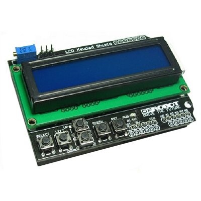
I also bought the DFRobot LCD Keypad Shield at the same time so I would have something to display data on and some keys for control. I didn't select very carefully as it uses 8 pins to acheive this and there may have been better choices.
On the whole I am happy with it but because it is designed for Arduino it requires some modification for it to work with Netduino.
The module is the DFRobot DFR0009
http://www.dfrobot.c...t&product_id=51
For those not familiar with this shield it connects to a common 16x2 LCD module using a 4-bit interface. With enable and reset that brings the pin count to 6 pins for the LCD.
The backlight is driven by a 7th pin via a transistor. This is a PWM pin which simplifies adjusting backlight intensity.
So far so good.
The keypad is where the mod is required. It consists of 5 buttons labeled select, up, down, left,right.
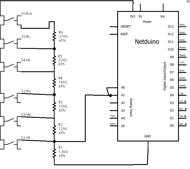
The buttons tap into a string of resistors and pull the Analog input pin0 to different voltages depending on which button is pushed. The output is designed for Arduino so the analog levels for the buttons are spaced between 0 and 5v.
The voltage output when the left button is pressed and when no button is pressed is over 3.3v so it will register as 1024.
My first attempt to mod the shield was to pull out the 5v pin and bridge the Vcc to the 3.3V pin. This fixed the keypad OK but the LCD contrast was no good. The text was just readable with the contrast pot at one end of its range. The HD44780 can run on 3.3v but not this LCD module.
So I reversed that mod and looked for another way.
In the end I settled on removing the 2k resistor at the top of the chain that links between 5v and the analog pin0
The 2k resistor is an SMD chip resistor thet is located under the LCD module but it can easily be reached with a soldering iron.
Then I made a new connection with a 1500ohm resistor between 3.3v and the analog pin0.
The resistance change to 1500ohms helps to maintain the even separation of the voltages generated.
With the new setup the switch presses theoretically generate the following ADC values, mine were all within a few counts of these.
None=1024
Select=796
Left=578
Down=397
Up=184
Right=0
If you are coding the thresholds to check against are 90,290,490,690 and 910.
Check the sample code for Arduino to see how it's done.
Here are some photos that should make things clearer.
This one shows the "202" resistor to be removed
DSC04881.JPG
This shows where to add the 1500R resistor
DSC04884.JPG
This shows the picture from the DFRObot website. My unit looks different but it still functions the same.
LCD&KeyPad_Shield.jpg
The library I used was the microliquidcrystal library
The LCD provider settings are below
//Keypad connected to Analog pin 0
AnalogInput keys = new AnalogInput(Pins.GPIO_PIN_A0);
//backlight connected to D10
// create the transfer provider
// Initialize the library with the numbers of the interface pins
PWM backlight = new PWM(Pins.GPIO_PIN_D10);
var lcdProvider = new GpioLcdTransferProvider(Pins.GPIO_PIN_D8, Pins.GPIO_PIN_D9,
         Pins.GPIO_PIN_D4, Pins.GPIO_PIN_D5, Pins.GPIO_PIN_D6, Pins.GPIO_PIN_D7);


#15575 LCDKeypad 16x2 HD44780 Shield

Posted by Mike P on 17 July 2011 - 11:41 AM in Project Showcase

Hi All,
I've documented a simple mod to this DFRobot LCD Keypad Shield (DFR0009)
The mod gets the keypad working as intended.
http://forums.netdui...-keypad-shield/

I put the appropriate analog values into the code provided at the beginning of this thread.
The thresholds are chosen to be about mid way between one expected value and the next and are typically 90-100 counts from the expected values so it should be quite reliable.

            /// <summary>
            /// Gets an enumeration of the key press at the current time.
            /// Can only be used if the LCD has been initialised with the true parameter.
            /// </summary>
            /// <returns></returns>
            public static Keys GetKey()
            {
                if (!analogInitialised) throw new Exception("Analog input is not Initialised");

                int i = AnKey.Read();

                if (i > 910)//expected value = 1024
                    return Keys.None;

                if (i < 90)//expected value = 0
                    return Keys.Right;

                if (i < 290)//expected value = 184
                    return Keys.Up;

                if (i < 490)//expected value = 397
                    return Keys.Down;

                if (i < 690)//expected value = 578
                    return Keys.Left;
                //expected value = 796
                return Keys.Select;

            }


#15914 Unable to deploy without disconnect\reconnect USB cable

Posted by Mike P on 26 July 2011 - 10:00 AM in Netduino Plus 2 (and Netduino Plus 1)

Same thing happens to me. If I hit the reset button then the I need to replug the usb connection before visual studio will reconnect to it. Running WinXP32. NetduinoPlus 4.1.0.6


#15994 ADC value divide by 1024 or 1023

Posted by Mike P on 28 July 2011 - 11:35 AM in Netduino 2 (and Netduino 1)

Everything Mario says is correct but I think he missed the question slightly. The ADC returns a value from 0 to 1023 not 0 to 1024. 0 to 1023 is 1024 different values because zero is a value too. so ADC value of zero corresponds to 0v and ADC value 1023 corresponds to 3.3v That is why you divide by 1023 and not 1024.


#15995 Initializing Brushless Motor problem

Posted by Mike P on 28 July 2011 - 11:55 AM in Netduino 2 (and Netduino 1)

I think that the netduino outputs all go high for a period during reset. This is probably being seen as the throttle not at zero by the ESC. I think most ESCs must be connected with the throttle at zero or they won't work. This is for obvious safety reasons. You could need to use some external gate to block the PWM output from the ESC until you are ready to output a proper servo command signal. Since you have 4 ESC outputs maybe use a quad XOR gate with 1 input of each gate connected together to another output pin that functions as an enable when it is low? This has the advantage of also buffering the servo signals from 3.3 up to 5 volts if you choose.


#15999 ADC value divide by 1024 or 1023

Posted by Mike P on 28 July 2011 - 12:26 PM in Netduino 2 (and Netduino 1)

Thanks, CW2 for taking the time to explain that. Mario didn't miss anything either. So we should be dividing by 1024 and not 1023. So... for an ADC value of "n" (assuming Aref=3.30v) n*3.3/1024 < voltage < (n+1)*3.3/1024 So to calculate a voltage that represented the ADC value with the least quantising error you need to add 1/2 an LSB to the value. voltage(mV) = (n+0.5)*3300/1024 quantising error = ±0.5*3300/1024 = n * 3.22265625 + 1.6 quantising error = ±1.6mV I get what Mario was saying about there being other sources of error eg Aref and conversion error. Do I have this right CW2 and Mario?


#16003 PWM demystified

Posted by Mike P on 28 July 2011 - 12:50 PM in Netduino 2 (and Netduino 1)

Since noone has offered ant solution to this, what about using I2C or SPI bus to do it? You could buffer up a command to send 1024 bits and change the number of 1s to adjust the pulse width. I don't know what control you have over the bus speed though.


#17085 Help with Proper Servo Driving

Posted by Mike P on 26 August 2011 - 09:09 AM in General Discussion

Another solution is to put 3 1N4007 diodes in series. The forward voltage drop is 0.7V each so the output would be 6.9V


#17234 AD5206 Digi Pot with SPI code....?

Posted by Mike P on 29 August 2011 - 12:36 PM in General Discussion

Hi CableGuy, I have added some info on SPI to the Wiki since you first posted. I hope you will find it useful. search for SPI on the wiki.


#17235 Six Button Interface for LCD Menu System.

Posted by Mike P on 29 August 2011 - 01:37 PM in General Discussion

The resistor network works pretty well. I have a DF Robot shield which uses this. That shield has Up,Dn,Left,Right,Select and Reset(The ultimate cancel?) One thing that may be a limitation is that it needs to be polled. You can't trigger an interrupt from an analog input pin. but you could use 2 pins, one as an interrupt port and the other as an analog input and feed the signal into both. for a digital IO pin voltages over 2.0v are a logic high so arrange the reseistor network so that a voltage of 0v for no keys pressed and voltages of 2.0 - 3.3v for the 6 keys. That's 260mv spacing. I haven't done the math but that sound like plenty of discrimination. The digital pin would be used to trigger an interrupt on a rising edge. Multiple keys being pressed simultaneously can be detected as long as the first key has a lower voltage than the second key. Usually when you use multiple keys simultaneously you hold one and press the second. I think that you should be able to implement more than 6 keys with interrupt on keypress and using only 2 pins.


#17279 Six Button Interface for LCD Menu System.

Posted by Mike P on 30 August 2011 - 04:12 PM in General Discussion

Now I've got to put my money where my mouth is! This should work but untested 6key IF_bb.png 6key IF_schem.png I tried to put a table in below but the TABs get stripped out so it's in CSV form instead. The table below gives the resistor values, The total resistance when the button is pressed, The voltage on the analog input, The ADC reading, The difference between the ADC value for this button and the next one up, and the suggested cut-off value to use when deciding which button has been pressed I even managed to keep to common value resistors and get very even separation between the voltages. Vcc=3300mV Button,Resistor,Total R,mV,ADC,delta,cutoff Cancel,1500,1500,3300,1024,,986 Right,120,1620,3056,948,76,908 Left,150,1770,2797,867,81,827 Down,180,1950,2538,787,80,747 Up,220,2170,2281,707,80,668 Select,270,2440,2029,629,78,315 None,,,0,0,629, In the schematic the second analog input pin would actually be used as a digital interrupt pin and could be on any of the GPIO pins. Its not necessary if you don't mind polling the analog input continuously.


#17286 Unable to deploy without disconnect\reconnect USB cable

Posted by Mike P on 30 August 2011 - 09:47 PM in Netduino Plus 2 (and Netduino Plus 1)

I thouth I would give this thread another kick to see if anyone else has any ideas. Is this behaviour normal then? Does everyone just unplug their netduino every time they deploy? I've tried all the available firmwares in the hope this might be a bug that has been addressed. 4.106 through to 4.2RC1


#17499 Wiki tutorial on SPI

Posted by Mike P on 04 September 2011 - 01:37 AM in General Discussion

Hi Mario, Thanks for adding the example. I think that a tutorial on using the 74HC595 is worthy of being a wiki topic in its own right. Can I suggest that you copy the tutorial to a new topic and link to that from the SPI configuration topic. This bit is not quite correct: "In the below picture there are the four possible combinations of Clock_Edge (NCPHA) and Clock_Idle (CPOL)" The NCPHA and CPOL bits used by the processor to control the SPI transfer do not map directly to the Clock_Edge and Clock_Idle parameters. It is not true to say that Clock_Edge==NCPHA. If CPOL==1 then Clock_Edge = !NCPHA It is correct that CPOL and NCPHA select 1 of four SPI modes and Clock_Edge and Clock_Idle have the same function. It would be better to show an excerpt from the 74HC595 datasheet and highlight what to look for.


#17521 Wiki tutorial on SPI

Posted by Mike P on 04 September 2011 - 12:31 PM in General Discussion

My English could be better and it is my firt language. What I meant to say was CPOL and NCPHA select 1 of four SPI modes and Clock_Edge and Clock_Idle also select one of 4 SPI modes.


#17567 What is this called?

Posted by Mike P on 05 September 2011 - 09:17 AM in General Discussion

2011-09-05_2058.jpg This would be my guess.(see labels on photo) The GND plane is pretty obvious - large filled area. There is a cap between GND and what I would assume is VCC VCC is also supplied to one pin of the sensor via a resistor. This would be a current limiting resistor for the LED side of the light gate. The detctor side appears to have a connection to VCC and GND and two ouptuts. These are normally called A and B and are 90° out of phase. This allows you to work out which direction the sensor is moving. If you think of the output as a 2-bit binaty value then the signal would 0-1-3-2 going in one direction and 2-3-1-0 in the other direction.


#17702 What is this called?

Posted by Mike P on 07 September 2011 - 01:42 AM in General Discussion

This would be a guess but there was probably another sensor conected to that 3 pin connector. Maybe a home position sensor or something.
The decoupling cap serves to smooth out the power supply. It acts like a shock absorber on the supply voltage. Without it small spikes on the power supply would be created whenever loads were switched on and off and these spikes might be transfered to the output signal.
The spikes on the output could be mistaken for real output transitions and cause the encoder to lose its count.

I posted some code on the Wiki last night for a rotary encoder. Chances are that it would work fine with your strip as well.
http://wiki.netduino...oder-Input.ashx


#17739 Pinout Cards

Posted by Mike P on 08 September 2011 - 04:29 AM in General Discussion

Thanks Tecchie,
Thanks also Inquisitor for bringing this to the top again.
I wonder how many more gems like this are buried in the forum archives.
I have taken the liberty of copying this to the Wiki so that it will remain readily available for all.

http://wiki.netduino...nout-Cards.ashx


#17750 SPI bug report (NETMF bug)

Posted by Mike P on 08 September 2011 - 11:40 AM in Beta Firmware and Drivers

Hi I think this is a bug in the netMF code. Would any of you code gurus like to have look and tell me if you agree?
Feel free to visit codeplex and vote.
http://netmf.codeple...m/workitem/1219

AT91_SPI_Driver::Xaction_Stop() has CS release sequence reversed

After the SPI transaction completes the Chip Select should be released before setting MOSI, MISO and SCLK to their idle levels.
in 4.1 and 4.2RC2 the MOSI and SCLK pins are both set low before CS is deactivated.
I am not sure but perhaps SCLK should be set low or high to honour the Clock_IdleState setting.
The file is C:\MicroFrameworkPK_v4_2\DeviceCode\Targets\Native\AT91\DeviceCode\AT91_SPI\AT91__SPI.cpp
Lines 376-384 should be moved up to line 342
This would only cause a problem for slaves where the Clock_IdleState was true. In this instance an unwanted clock edge is sent before chip select is released. Depending on how the slave has been implemented this may have no effect.

Here is a capture of the SPI transfer and you can see MOSI and SCLK being set low before CS is released.traces are SCLK, MOSI, MISO, CS.
single sample.png


#17952 EM406a not fixing satelites

Posted by Mike P on 14 September 2011 - 12:08 AM in General Discussion

Did you take it outside? My experience is that very few GPSs work inside.


#17953 Combining Pins

Posted by Mike P on 14 September 2011 - 12:30 AM in General Discussion

NETMF may not have a built in class but GHI have implemented a parallelPort class for their products on NETMF.
I wonder if this could be ported into the Netduino firmware? They also have an outputCompare class that looks pretty useful.
http://www.ghielectr...tion/Index.html

Oh well...


#17965 3.3v, 5v, Various Ports and Components, oh my.

Posted by Mike P on 14 September 2011 - 04:09 AM in General Discussion

Welcome aboard. One of the first steps in learning is figuring out what questions to ask. Judging from your post you have that well underway. You will find many basic tutorials on the net. There's dozens of them. A basic understanding of the function of resistors, diodes and capacitors will answer a lot of your questions. I would make sure you understand why a resistor is required before you connect your LED to your netduino. There is no overcurrent protection on the netduino outputs which means you can burn them out. Good luck


#17966 Where is DateTime?

Posted by Mike P on 14 September 2011 - 04:12 AM in General Discussion

Have you seen this post?
http://forums.netdui...uino-date-time/


#18037 Pin 4 can't be used at a high speed?

Posted by Mike P on 15 September 2011 - 09:48 AM in Netduino 2 (and Netduino 1)

Hi Stefan, since you've brought this back to the top again I'll add my 2cents. If you are interested I think I can explain why pin4 does not work as a chip select. The SPI driver is part of NETMF code. SecretLabs have a few lines of code they have added but by and large it is untouched from the NETMF distributed version. The AT91 core SPI peripheral supports 4 pins as hardware chip select pins CS0-CS3. CS0 is also used as a slave select (NSS) in slave mode. Pin4 is the pin that connects to this CS0/NSS peripheral output. Within the driver code there is a block of code that would convert pin 4 from its GPIO function to its SPI peripheral function if you pass pin4 as the chip select. This line of code is commented out. There is also a code block that sets the CS pin to the appropriate state before and after the transfer. This block of code doesn't get executed if you use GPIO_PIN4 or GPIO_PIN_NONE. It appears as though the programmer intended to support use of pin 4 as a peripheral hardware chip select and any other pin as a software chip select. But when they couldn't get CS0 working they commented it out in one place but not the other. I think I can see why it wouldn't have worked too. As written the CS line would have pulsed inactive between each character which would have messed things up in most applications. So until someone fixes the SPI class properly you will just have to accept that pin4 can't be used for Chip select. If you are interested to look yourself the driver code is in the porting kit here: C:\MicroFrameworkPK_v4_2\DeviceCode\Targets\Native\AT91\DeviceCode\AT91_SPI\AT91__SPI.cpp


#18044 Compiling firmware

Posted by Mike P on 15 September 2011 - 12:55 PM in Netduino 2 (and Netduino 1)

There are several really good posts buried in the forum on how to compile the Netduino firmware from source code.
I've managed to get as far as this error:

C:\GCC\bin\arm-none-eabi-ld.exe: C:\MicroFrameworkPK_v4_1\BuildOutput\THUMB\GCC4.2\le\FLASH\release\Netduino\bin\tinyclr.axf section ER_FLASH will not fit in region LR_FLASH
 C:\GCC\bin\arm-none-eabi-ld.exe: region LR_FLASH overflowed by 65128 bytes

Now I have read this very helpful post by CW2:
http://forums.netdui...dpost__p__10332

And I understand that I have to adjust the blockrange for the code.

What I am stuck on is where do I find the size of the ER_FLASH file since it does not get created when the build fails.

In CW2's post he says "but our firmware is 0x50ADC bytes" but I don't know where that figure came from.
How do I find the size of the firmware so that I can know how big to make the BlockRange?


#18056 Compiling firmware

Posted by Mike P on 15 September 2011 - 07:49 PM in Netduino 2 (and Netduino 1)

Thanks CW2. That makes a lot of sense. Success. I compliled and uploaded firmware from source for the first time.


home    hardware    projects    downloads    community    where to buy    contact Copyright © 2016 Wilderness Labs Inc.  |  Legal   |   CC BY-SA
This webpage is licensed under a Creative Commons Attribution-ShareAlike License.