Has anyone got any experience with these units?
DSO Nano v2
Stuart Crawshaw's Content
There have been 60 items by Stuart Crawshaw (Search limited from 22-May 23)
#15735 USB Oscilloscopes?
 Posted by
on 20 July 2011 - 10:56 AM
in
General Discussion
Posted by
on 20 July 2011 - 10:56 AM
in
General Discussion
#15734 I2c problems interfacing TPIC2810 Led Driver
Posted by
on 20 July 2011 - 10:48 AM
in
Netduino 2 (and Netduino 1)
I see, thanks for the link. But if I understand it correctly, this was supposed to reveal a possible bug (in A4/A5 multiplexing), which was not confirmed (?)
Agreed, but worth a try

I am in aggreement that Matteo does need a pull-up on the SCL line too...
What i am not aware of is the calculation needed to work out the value of the resistor needed, can you shed some light?
#15729 I2c problems interfacing TPIC2810 Led Driver
Posted by
on 20 July 2011 - 10:25 AM
in
Netduino 2 (and Netduino 1)
Hi CW2,[*]I don't understand exactly how instantiating and disposing OutputPort objects is supposed to 'reset' the ports, the pin is set back to input state ('floating high') when disposed. I would start with commenting this code out.[/list]
This was suggested by Chris Walker, as he advised in another post that there could be a bug in the firmware and this sometimes fixes it.
Link Here - At the bottom of post #2
#15727 I2c problems interfacing TPIC2810 Led Driver
Posted by
on 20 July 2011 - 10:11 AM
in
Netduino 2 (and Netduino 1)
Hi again Matteo,
Did you try with the pull-up on the SCL line as well as the SDA?
Also,
Im not sure of the calculation needed to work out the resistor values for the pull-up resistors (sure someone could teach us both there)
But looking through the various articles it seems it can play a big part, See Here
Also, Could you advise where you attached your scope probes, just so any of these guys on here can replicate how you have your setup to see how their tests differ.
Additionally, could you explain to me the setup of your A0-A2 pins (just for my knowledge) why you set them up in such a way?
From what i can see, these would result (with the switches made) in a Logic-High? where as the address you supplied in code is all A0-2 pins being in a LOW state.
Hope we can get this resolved for you.
P.S. My old old old scope packed in last night so im on the lookout for a new fangled replacement and couldnt test my I2C signals as i said i would.
Did you try with the pull-up on the SCL line as well as the SDA?
Also,
Im not sure of the calculation needed to work out the resistor values for the pull-up resistors (sure someone could teach us both there)
But looking through the various articles it seems it can play a big part, See Here
Also, Could you advise where you attached your scope probes, just so any of these guys on here can replicate how you have your setup to see how their tests differ.
Additionally, could you explain to me the setup of your A0-A2 pins (just for my knowledge) why you set them up in such a way?
From what i can see, these would result (with the switches made) in a Logic-High? where as the address you supplied in code is all A0-2 pins being in a LOW state.
Hope we can get this resolved for you.
P.S. My old old old scope packed in last night
so im on the lookout for a new fangled replacement and couldnt test my I2C signals as i said i would.
#15693 New Soldering Iron
Posted by
on 19 July 2011 - 05:00 PM
in
General Discussion
I personally use Hakko soldering equipment, and have been very happy.
They have a new entry-level soldering iron which is less than $100. I haven't used it, but if it's anything like their normal gear it's probably a solid buy.
http://www.adafruit.com/products/303
There are a ton of options out there... What does everyone else recommend?
Chris
Thanks for the suggestion Chris, not sure if these are available in the UK though, but its a good start (i could find another reputable manufacturer and look for similar if not better specs for the same price range).
#15691 Six Button Interface for LCD Menu System.
Posted by
on 19 July 2011 - 04:47 PM
in
General Discussion
Back in the 90's the Parralax stamp used 1 pin for 8 switches.
Bad fritzing but will give you an idea.
In this example (cant find single pin of gnd plane)
The resistors are connected to an analoge in pin and the capacitor end is connected to gnd (or however the netduino handles it)
The whole thing reads as a potentiometer so is simple to work.
Going by what I have lurned so far you may be able to drop the cap.
I hope this helps with your button issue.
Thats an interesting idea, thank you.
Ill keep this in mind, wouldn't this idea how ever require some slight pre-programming of the values per switch and also, if i press multiple switches at once, would this not cause an issue?
#15687 Six Button Interface for LCD Menu System.
Posted by
on 19 July 2011 - 03:34 PM
in
General Discussion
You will get an error because both will try to initialize the SPI bus.
The code I have would (in thory) use a centralised "shared" SPI bus (a static property of the main program, initialized on startup). Could i not modify it to work with the "shared bus"?
#15683 Six Button Interface for LCD Menu System.
Posted by
on 19 July 2011 - 03:10 PM
in
General Discussion
If you want to combine that LCD driver with other SPI devices (which is the case in my sample above) you need to use another LCDTransferProvider. I got one ready for that. Will upload it later today.
If i understand that correctly, i couldnt use the multiplexing solution as well as have an LCD on the SPI bus?
I read your post and it looks AMAZING! Just want i was looking for, but on a smaller scale
 .
.
#15681 Six Button Interface for LCD Menu System.
Posted by
on 19 July 2011 - 02:58 PM
in
General Discussion
A few months ago I published a post about multiplexing:
http://forums.netdui...h-the-netduino/
Also HD44780 LCDs can work over 74hc595 IC's.
Thanks, i shall have a read through that post,
I currently have the LCD working via a 74HC595 using the SPI bus, so its just the buttons i need to get working in a conservative fasion.
So, Ill have a read and get back to you.
Thanks again.

#15679 Six Button Interface for LCD Menu System.
Posted by
on 19 July 2011 - 02:51 PM
in
General Discussion
Hi all,
Here is the outline,
I want to have a menu system accessible by buttons on my project. The display will be a 20x4 LCD Display and there will be 6 buttons as follows:
Now the basic idea of how these would work is have an interrupt port setup for each button (but thats 6 ports!). So now the question,
How could i achieve this, but only use the minimal number of ports?
I though about using a PISO Shift Reg, but then remembered it would need a clock etc and someway for the ND to know that data is coming in (i think).
I then there is the Matrix style setup but i would only save 1 pin (2 cols and 3 rows = 5 lines).
Any suggestions, fancy IC's or fancy components that will let be achive this goal?
Thanks for your continued support.
Stuart
Here is the outline,
I want to have a menu system accessible by buttons on my project. The display will be a 20x4 LCD Display and there will be 6 buttons as follows:
- UP
- DOWN
- LEFT
- RIGHT
- OK
- CANCEL
Now the basic idea of how these would work is have an interrupt port setup for each button (but thats 6 ports!). So now the question,
How could i achieve this, but only use the minimal number of ports?
I though about using a PISO Shift Reg, but then remembered it would need a clock etc and someway for the ND to know that data is coming in (i think).
I then there is the Matrix style setup but i would only save 1 pin (2 cols and 3 rows = 5 lines).
Any suggestions, fancy IC's or fancy components that will let be achive this goal?
Thanks for your continued support.
Stuart
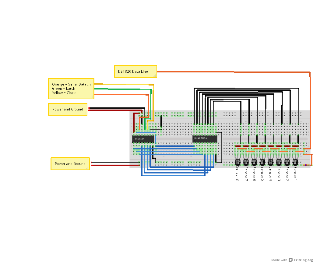
#15678 DS18*20 Temperature Sensor Auto Identity Circuit
Posted by
on 19 July 2011 - 02:36 PM
in
General Discussion
Ive just been looking through some components and decided to go with a ULN2803A Transistor Array.
This array has built in 2K7 resistors on the base of each transistor, which if my calculations are correct is just about the right region (I calculated 2.5k would be needed to use the transistors as a switch).
So if any of you guys would be so kind and let me know if this seems to be correct from an electronics point of view (i.e. it wont blow up or not work at all)
Attached Thumbnails
#15674 New Soldering Iron
Posted by
on 19 July 2011 - 12:27 PM
in
General Discussion
Hi All,
Its me again OK, so i have finally given up on my very very cheap apparently "temperature controlled" soldering iron (its either too hot or too cold)
So, as the title of this thread suggests, i am looking for a new one but on a budget.
Im not looking to spend more than £100 (may be less) but want a decent solding iron with a digital display of some sort to show the current temperature...
So for you standard hobbyist who will be soldering through-hole components on to vero-board such as transistors, resistors etc (none of the surface monut stuff)
What would you guys suggest? What wattage is good? if 70W too low?
Etc etc etc....
Thanks guys.
OK, so i have finally given up on my very very cheap apparently "temperature controlled" soldering iron (its either too hot or too cold)
So, as the title of this thread suggests, i am looking for a new one but on a budget.
Im not looking to spend more than £100 (may be less) but want a decent solding iron with a digital display of some sort to show the current temperature...
So for you standard hobbyist who will be soldering through-hole components on to vero-board such as transistors, resistors etc (none of the surface monut stuff)
What would you guys suggest? What wattage is good? if 70W too low?
Etc etc etc....
Thanks guys.
#15640 Full-featured driver / test code for the Maxim DS1307 real-time clock
Posted by
on 18 July 2011 - 03:49 PM
in
Project Showcase
Hi, I’m new here. I’m having a hard time trying to display time and date on a LCD.
I have wired up a Netduino, DS1307 RTC module and a 20x4 HD44780-controlled LCD on a breadboard. I can get “Hello World” to appear on the LCD, but not time and date.
Any help is welcome. Thanks in advance.
Hi,
Could you describe the problems you are having? I.E. does it just display garbage, Not at all etc...
And code examples would be a great help also.
Thanks,
#15536 Pyrotechnic Sequencer
Posted by
on 15 July 2011 - 04:22 PM
in
Project Showcase
I've always used Yenka (was previously called Crocodile Clips) that I still have a student licence for from school .. 10 years ago. If there's an open source sim that anyone would recommend I check out,that would be great.
Just for info, If you didnt know already, Yenka has a free license for Home users
#15531 DS1307 Sparkfun I2C
Posted by
on 15 July 2011 - 11:43 AM
in
Netduino 2 (and Netduino 1)
Yes, I connected everithing well again......thank you very much for wasting your time with my problem, shure that the problem it´s a little detail(a dumb detail shure) but if I can i would try to put a photo of whow I´ve got the connections.........
You are not wasting our time i assure you. The success of a good community is mutual help. No problem is dumb, its all down to experience (I am not an expert in electronics at all, im a coder)
No question, big or small is a dumb question. The most intelligent thing people can do when unsure is to ask
P.S. Did you see my code example i posted on the previous page (hate pages
) the attached library/wrapper may well prove useful.
#15527 DS1307 Sparkfun I2C
Posted by
on 15 July 2011 - 11:35 AM
in
Netduino 2 (and Netduino 1)
I updated the firmware to 4.1.1 beta version but I´m in the same way, it doesn´t work neither with my code not with that one you posted, it gives me the same error that i have told you before..........
OK,
Can you post the code you have used, please bare in mind that the transaction for a read should include an initial write (to write the address of the register to be read) and then a read.
Please see this excract of code from the FusionWare I2C Library (attached).
/// <summary>Performs a common Write-repeatstart-read command response operation</summary>
/// <param name="Config">Configuration for the bus during this operation</param>
/// <param name="WriteBuffer">Buffer containing data to write</param>
/// <param name="ReadBuffer">Buffer to receive data. The Length property of ReadBuffer determines the number of bytes to read</param>
/// <param name="TimeOut">Millisecond time out value</param>
/// <remarks>
/// Many I2C devices have a simple command response protocol of some sort
/// this method simplifies the implementation of device specific drivers
/// by wrapping up the I2CTransaction creation and timeout detection etc.
/// to support a simple command/response type of protocol. It creates a write
/// transaction and a read transaction with a repeat-start condition in between
/// to maintain control of the bus for the entire operation.
/// </remarks>
/// <exception cref="T:System.IO.IOException">Operation failed to complete</exception>
public void WriteRead(I2CDevice.Configuration Config, byte[] WriteBuffer, byte[] ReadBuffer, int TimeOut)
{
    ThrowIfDisposed();
    lock(this.Device)
    {
        this.Device.Config = Config;
        I2CDevice.I2CTransaction[] xacts = new I2CDevice.I2CTransaction[] {
            I2CDevice.CreateWriteTransaction(WriteBuffer),
            I2CDevice.CreateReadTransaction(ReadBuffer)
        };

        // I2CDevice.Execute returns the total number of bytes
        // transfered in BOTH directions for all transactions
        int byteCount = this.Device.Execute(xacts, TimeOut);
        if(byteCount < (WriteBuffer.Length + ReadBuffer.Length))
            throw new System.IO.IOException();
    }
}
EDIT: Corrected spelling of FusionWare
Attached Files
-
 FusionWare.zip 11.1KB
21 downloads
FusionWare.zip 11.1KB
21 downloads
#15521 DS1307 Sparkfun I2C
Posted by
on 15 July 2011 - 09:49 AM
in
Netduino 2 (and Netduino 1)
Can't confirm nor contradict it; I didn't wrote the code, only successfully implemented it. But I used the 4.1.1 beta firmware at that time.
Ahh ok,
I believe it would thought, makes sense that it would to me.
If it is the case, then the read command would be executed without an address being sent to the device.
#15518 DS1307 Sparkfun I2C
Posted by
on 15 July 2011 - 09:42 AM
in
Netduino 2 (and Netduino 1)
Also i noticed this in your code
After each Execute, it would produce a stop bit. Thus cancelling the address it was at (I think) and the read may not know where to reference.
Stefan, Can you confirm this? as i dont have my DS1307....yet...
I2CDevice.I2CTransaction[] tran = new I2CDevice.I2CTransaction[]{tran_write};

            int data = RTC.Execute(tran, 100);

            Debug.Print("\nThe number of data transfered is: "+ data.ToString());

            tran = new I2CDevice.I2CTransaction[] { tran_read };

            data = RTC.Execute(tran, 100);
After each Execute, it would produce a stop bit. Thus cancelling the address it was at (I think) and the read may not know where to reference.
Stefan, Can you confirm this? as i dont have my DS1307....yet...
#15516 DS1307 Sparkfun I2C
Posted by
on 15 July 2011 - 09:39 AM
in
Netduino 2 (and Netduino 1)
Just to add as i dont know if its been touched on in this thread.
The DS1207 requires the repeated start support of one of the custom built FW's (Im using 4.1 with CW's OneWire Library)
Can you confirm if you are using the stock firmware or a custom build with the repeated start bit support?
#15514 Another LED "Hello world!" program
Posted by
on 15 July 2011 - 09:27 AM
in
Project Showcase
Cool,
I look forward to seeing the outcome
#15512 Soldering Techniques For Small Components
Posted by
on 15 July 2011 - 09:06 AM
in
General Discussion
That's true indeed.
Consider that any heat sink close to the soldering point will cool the iron temperature. That could give a bad melting and a matt/crystalled result. Along this way, a regulated iron guarantee always a good soldering.
Cheers
Thanks for the heads up.
Im currently using a variable temperature gas soldering iron, it seems to do the job quite well. I manage the tip temperature with an infrared thermometer.
#15509 Another LED "Hello world!" program
Posted by
on 15 July 2011 - 08:48 AM
in
Project Showcase
Transistors are there because GPIO pins on Netduino have 8mA limit, which is not enough to power a LED.
I did not realise this, thank you for the information. Although i have plugged an LED in series with a resistor on one of the GPIO pins and it worked, Could this be drawing more current than it should?
If you light up one led at once there's no need for many resistor. When the other leds are off it's like they are disconnected from the circuit.
However, when your program wants to light 2+ leds, it's better to consider one resistor per led. (read further)
Thats what i was trying to get at, The video and description shows only one LED on at a time so i though it would be easier to use just the one resistor.
So, if you use ONE resistor for many leds, you may light more than one, but the more you light the less they shine. That's because the current is always the same and be "shared" among all the led involved in the lighting.
This in theory could make a good effect (if done quick enough) of the LED's fading in/out and the next one it lit and the other go off?
Thanks Guys and thanks for the corrections to my understanding of this circuit.
#15506 Soldering Techniques For Small Components
Posted by
on 15 July 2011 - 08:37 AM
in
General Discussion
Thank you all so much for your input, this has been very helpful.
Thank you Dan for the links you posted, I was looking for something like that. Especially since the croc-clips would act as a kind of heat shunt to protect the component being soldered.
Regards,
Stuart
#15486 Soldering Techniques For Small Components
Posted by
on 14 July 2011 - 05:20 PM
in
General Discussion
The DS1820 i am referencing is a 3-pin package similar to that of the 2n2222 transistor.
By techniques i mean how would you do it, do you have any tips or tricks etc...
#15484 Soldering Techniques For Small Components
Posted by
on 14 July 2011 - 04:33 PM
in
General Discussion
Hello Everybody,
General question to go out ot everyone regarding Soldering Techniques....
When soldering small components, for example: the wires on to the pins of a DS1820 sensor, how do you go about this?
Ill also open this question up to everyone to share any other soldering Techniques they use when soldering other things too!
Thanks again guys, Cant wait to see how you get yours done!
--------
Stuart.


