count me in!
mcinnes01's Content
There have been 82 items by mcinnes01 (Search limited from 29-April 23)
#52619 A virtual hack night
 Posted by
on 06 September 2013 - 10:37 PM
in
General Discussion
Posted by
on 06 September 2013 - 10:37 PM
in
General Discussion
#52509 Call for Secret Labs to Kick Start Go! Bus
Posted by
on 02 September 2013 - 10:46 PM
in
General Discussion
Hi,
I have been a happy user of Secret Labs products for many years, I have enjoyed the fantastic, friendly and helpful community and Secret Labs energy and commitment to improve their products.
Now I feel it is the communities chance to help Secret Labs...
I would like to propose that Secret Labs start a Kick Starter campaign to help fund the development of the Go! Bus protocol which is holding back many avid netduino users and the exciting new products Secret Labs have on backlog. The community have all been waiting patiently for ethernet, SD and the Gadgeteer hub for sometime and it seems focus has shifted and the forums have gone a little quiet.
I would like to know the viability to allow the community to "give a little to get a little", by funding Secret Labs so they can employ some additional resources to either work on the Go! Bus protocol, or work on the AGENT smart watch, freeing up other resource to work on Go! Bus.
I would love to start getting some use out of my N Go! and would love to see the netduino forums that bustling hive of community interest they were previously.
What are your thoughts on this?
Many thanks,
Andy
#52600 Call for Secret Labs to Kick Start Go! Bus
Posted by
on 05 September 2013 - 09:43 PM
in
General Discussion
I would as ever still love to see 1-wire, maybe even a can-bus module? And perhaps a wifi module?
Although I feel a chicken and egg argument coming on....
Which **should** come first Go! Bus 1.5 or new modules?
If you develop a module you would have to write your own firmware which would be a port around Go! bus 1.0. Then what happens when the generic firmware comes out for the STMs with 1.5?
Chris if funding is not a route, but developing modules is, can users have an update on where Go Bus 1.5 is.
It would be helpful to see:
- An up to date feature set
- Current status of the features
- Current issues
- A detailed definition of the architecture and how the various functions that are complete work and how you expect or propose the outstanding features to fit in.
Are SL happy to share this level of detail and perhaps the code for users to contribute/test?
There are a fair few people with STM discovery boards, I guess testing can be done for Go! bus 1.5 with an N Go! + STM discovery right?
Thanks again and I hope we can spark some community interest back in to Go! 
Andy
#52555 Call for Secret Labs to Kick Start Go! Bus
Posted by
on 04 September 2013 - 09:20 PM
in
General Discussion
@Juzzer you seem a pretty smart guy looking at your own STM board and your port of NETMF, I would love to see what you could develop for the Go! Maybe a Wifi Module or 1-Wire module or something all together previously unimagined?
@Chris if people like Juzzer were able to spend a little time how could they get involved with physically developing the Go! bus protocol?
Andy
#52554 Call for Secret Labs to Kick Start Go! Bus
Posted by
on 04 September 2013 - 09:11 PM
in
General Discussion
Hi Chris,
I completely understand the economics behind open source aren't quite as straight forward as standard commercial products and this is why I believe the community could dig in and help out...
Whilst Go! Bus may equally benefit from community input from some of the more advanced users I thought there may be a way some of us other users could help out. Whilst throwing money at a problem doesn't always fix it, I was interested in both the community's and Secret Labs opinion on how we could inject some help in to realising the Go! Bus dream. As Go! Bus is Secret Labs brain child its very difficult for people to necessarily contribute on a community platform and this is where my thought of the community and possibly potential hardware vendors helping fund this endeavour.
Hardware vendors can benefit from using Go! Bus once it is available to facilitate their own commercial products and ultimately this drives interest back in to the Netduino community. I completely understand that you can't invest more than the returns from sales of the Go! line in to developing it further, but without the new toys like ethernet etc I'm sure you would agree that Go! sales have slumped from the initial level of interest and this catch 22 situation of needing interested to drive sales, to fund development, to create interest, to drive sales.
This is where a possible funding scheme like kick starter could help Go!, Netduino and Open source hardware in general...
Kick Starter could be used to break the the vicious cycle and could enable Secret Labs to get an extra person working on the Go! line.
I guess if you could think in terms of what resources could benefit Go! and what would be required financially or otherwise, the community could work something out?
I would be happy to donate in this way, and you can either take the approach you did with AGENT, offering ethernet modules etc, or simply allow people to donate for Go! Bus 1.5 to become a reality sooner
Andy
#52620 Complete Home Automation from Multiple Devices
Posted by
on 06 September 2013 - 10:45 PM
in
Netduino Plus 2 (and Netduino Plus 1)
I am having 2 central locations, 1 in the loft and 1 in the cellar to avoid having to create a riser and to reduce cable runs. I will have a gigabit link between the 2 and am installing a 96 port patch panel in each to allow me to route things ad-hoc.
Each light will go back to these 2 points where I will have a distribution board. Relays will perform the switching all located centrally on the 2 distribution boards. This makes maintenance easy and reduces the number of points of failure. In house having a single or couple of points of failure is desirable as it means you don't have to start ripping up walls and floor boards.
Although CAT5 is going in, I may in most cases just use it for the the shielded twisted pairs. As there are 4 pairs you can send data and power down the same cable without creating too much noise. Also if you change your mind you can convert them to standard cat5 cables.
Check out some of my active threads for ideas.
Andy
#52601 Complete Home Automation from Multiple Devices
Posted by
on 05 September 2013 - 10:07 PM
in
Netduino Plus 2 (and Netduino Plus 1)
I am on the same quest as yourself currently....
Although I am running about 140 separate runs of cat5e.
Some will have wall plates (phone, ethernet) some go to devices, sensors, valves, switches, etc.
This all goes back to a patch panel so I can route and change the use as and when I want.
Also worth thinking about POE.
As I have recently learnt from Mario, SPI is not good over long distances and I have had flakey experiences with it in the past. Noise is a real issue.
This is true with i2c but to less of an extent and there are ways of reducing noise and its effects.
Something to perhaps ponder, to reduce the effects of resistance you will probably want to step your signal up to say 24v. This in itself creates noise and other complications, but solves the issue of running over long distances.
I will share what I learn from Mario and perhaps you can share your ideas?
Andy
#58371 Ethernet Module Update
Posted by
on 23 May 2014 - 09:34 PM
in
Netduino Go
Sigh, why don't you just get a cheap ass ENC28J60 module off ebay for < �3 and use the mIP library?
At least this is something that WILL get ethernet to the GO without doubt.
Module: http://www.ebay.co.u...=item20d966b102
I'm currently trying to get mIP working with M2Mqtt so I can get GO working with Mqtt, it would be cool to have a few other people helping explore this route
#58416 Ethernet Module Update
Posted by
on 27 May 2014 - 08:54 AM
in
Netduino Go
Well that's up to you I know its frustrating waiting ages and comms could definitely been handled differently by secret labs, but this is the situation which I'm sure is fairly common when developing new transport protocols especially with netmf ever evolving and having to work around the bugs that are inherited with it.
The suggestion of mip + an enc28j60 is a good cheap alternative or at least stop gap. It is from what I understand the same chip on the ethernet board we are all waiting on. Plus it uses spi, so you only really lose 1 pin for chip select if you use other spi modules and the multi spi library, so not much of a sacrifice. I got it working sharing spi with a gpio expander so I actually gained pins as opposed to lost pins. Also in terms of plug and play, bar a resistor and not having a 10 pin connector or shield format, its not far off. At least this way you can move on with your code and project in the mean time, then when the ethernet module lands, fingers crossed this year, you can simply switch out the mip code for the native network code.
Hth
Andy
I know its frustrating waiting ages and comms could definitely been handled differently by secret labs, but this is the situation which I'm sure is fairly common when developing new transport protocols especially with netmf ever evolving and having to work around the bugs that are inherited with it.The suggestion of mip + an enc28j60 is a good cheap alternative or at least stop gap. It is from what I understand the same chip on the ethernet board we are all waiting on. Plus it uses spi, so you only really lose 1 pin for chip select if you use other spi modules and the multi spi library, so not much of a sacrifice. I got it working sharing spi with a gpio expander so I actually gained pins as opposed to lost pins. Also in terms of plug and play, bar a resistor and not having a 10 pin connector or shield format, its not far off. At least this way you can move on with your code and project in the mean time, then when the ethernet module lands, fingers crossed this year, you can simply switch out the mip code for the native network code.
Hth
Andy
#54468 Ethernet Module Update
Posted by
on 04 December 2013 - 07:56 PM
in
Netduino Go
Hi,
Chris is there a planned release date for 4.3QFE1?
Are there fixes in this next release of netmf that are holding the next release of Go! Bus up?
Many thanks,
Andy
PS Roll on the new modules
#54494 Ethernet Module Update
Posted by
on 05 December 2013 - 07:42 PM
in
Netduino Go
I have a lot of confidence in the Go! range again, although we haven't seen many gizmo's and do-dads in the last year, in recent months various releases for shield base have come out. Also thanks to Chris for taking the feedback of the community (the good and the less compliment).
I think he has done a great job being patient and sympathetic to community frustration, whilst I'm sure secret labs have some of their own, waiting on netmf updates.
Whilst I too have been disappointed from time to time, the netduino products are great and other community members must be excited by the imminent prospect of new modules too! Plus QFE1 at the longest will be 3 months at a guess, so I think we have A LOT to be excited for in the not so distant future.
#52675 Ethernet Module Update
Posted by
on 09 September 2013 - 09:21 PM
in
Netduino Go
I often see books on amazon with a similar status? Still if 6 months is a realistic time scale for Go! Bus 1.5 it at least gives us a date to look forward to
#56328 Extensive driver for the MCP23S17 I/O expander
Posted by
on 24 February 2014 - 07:51 AM
in
Project Showcase
Hi Hanz,
That is much clearer, thanks and I welcome any constructive criticism
I am getting this error:
A first chance exception of type 'MCP23S17Lib.MCP23S17.MCP23S17Exception' occurred in Testspi1.exeAn unhandled exception of type 'MCP23S17Lib.MCP23S17.MCP23S17Exception' occurred in Testspi1.exeAdditional information: MCP23S17: Pin already in use: Port0000 Uncaught exception
On the throw exception in the code:
private void _RegisterPort(_Port pin) { int idx = (int)pin.Pin; if (_pins.Contains(idx)) throw new MCP23S17Exception("Pin already in use: " + pin.Name); // store it _pins[idx] = pin; }Not sure what I am missing?
Also I don't seem to be getting any output on the board? I can see there is power there, but in all my tests so far I have not lit an LED. The LED is connected to one of the digital pins on chip 1 and is then connected to the ground on the board. My first test to define and switch one port on constantly resulted in no output on chip one on any pin and there was out put on a few pins on chip 2. I will see if I can recreate that scenario.
I wonder if there hardware address isn't set correctly in my code?
Does this need to be a hex value and where would I set it?
Many thanks
Andy
#56592 Extensive driver for the MCP23S17 I/O expander
Posted by
on 02 March 2014 - 11:10 PM
in
Project Showcase
Carrying the multi SPI conversation on here...
Do you think it is possible to incorporate Steffan's multi spi mgr in to your MCP23S17 driver?
Thus making it possible to share with MIP without modifying MIP?
On another topic...
I was considering the use of the bus.
If I wanted to dynamically group pins/ports and abstract this further to allow me to create groups or "buses" across chips do you think this is possible.
Let me elaborate...
Am I correct in saying the use of a bus is to allow for multiple port changes to be made in one write, thus increasing speed and efficiency?
If this is correct, then I also understand that I can't make a bus spanning multiple chips, however if for example I wanted to change the state of 10 pins 5 on each chip, then I could create a class that identifies which pins are on which bus and perform 2 writes one for each bus?
This is obviously going to be more efficient than 10 separate writes and gives me the ability, for example to "turn off all lights" or "turn off everything".
Many thanks,
Andy
#56823 Extensive driver for the MCP23S17 I/O expander
Posted by
on 15 March 2014 - 06:41 PM
in
Project Showcase
Hi,
I have done a little testing and my adjustments seem to work in terms of implementing the standard multi SPI class as per the netmf toolbox.
Please see amendments attached.
Next task is to create a wrapper to handle the scenario of creating cross chip groups that leverage the bus functionality where possible.
Many thanks,
Andy
Attached Files
-
 MCP23S17.cs 55.46KB
7 downloads
MCP23S17.cs 55.46KB
7 downloads
#56311 Extensive driver for the MCP23S17 I/O expander
Posted by
on 23 February 2014 - 08:54 PM
in
Project Showcase
Hi Hanz,
Am I doing something wrong or is this where the bug lies with multiple chips?
I get an error on the line:
_spi = new SPI(new SPI.Configuration(xcsPin, false, 0, 0, false, true, spiSpeedkHz, spiModule));
From this bit of the driver:
/// <summary> /// Create a new instance of the MCP23S17 driver /// </summary> /// <param name="spiModule">SPI module to use</param> /// <param name="xcsPin">Chip select pin for SPI bus</param> /// <param name="irqPin">Interrupt pin</param> /// <param name="hwAddr">Chip hardware address</param> /// <param name="spiSpeedkHz">SPI clock speed in kHz</param> public MCP23S17(SPI.SPI_module spiModule, Cpu.Pin xcsPin, Cpu.Pin irqPin, byte hwAddr, uint spiSpeedkHz) { _spi = new SPI(new SPI.Configuration(xcsPin, false, 0, 0, false, true, spiSpeedkHz, spiModule));The error I get is:
#### Exception System.InvalidOperationException - CLR_E_INVALID_OPERATION (1) #### #### Message: #### Microsoft.SPOT.Hardware.Port::ReservePin [IP: 0000] #### #### Microsoft.SPOT.Hardware.SPI::.ctor [IP: 0022] #### #### MCP23S17Lib.MCP23S17::.ctor [IP: 0022] #### #### Testspi1.Program::Main [IP: 0023] ####A first chance exception of type 'System.InvalidOperationException' occurred in Microsoft.SPOT.Hardware.dllAn unhandled exception of type 'System.InvalidOperationException' occurred in Microsoft.SPOT.Hardware.dll
Any ideas?
Cheers,
Andy
#56819 Extensive driver for the MCP23S17 I/O expander
Posted by
on 15 March 2014 - 04:43 PM
in
Project Showcase
Hi Hanz,
No offence taken, I am taking your advice and investigating a little more before I repost. I have made a better test subject with a load of leds and am just reworking my changes to the code to get a proper test in. I should have some findings shortly so I will post back when I have something more substantial.
Many thanks,
Andy
#56228 Extensive driver for the MCP23S17 I/O expander
Posted by
on 20 February 2014 - 04:40 PM
in
Project Showcase
Hi
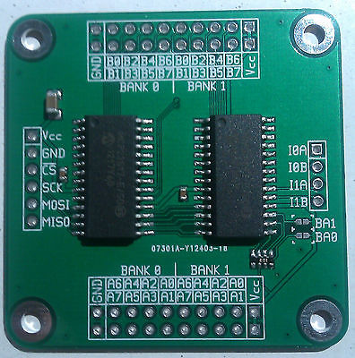
I have this board by majenko http://cgi.ebay.ie/w...em=191068114141
They have an arduino library here https://github.com/m...kotech/MCP23S17
I have also emailed them to find out if they have any details on the pins as requested.
I will let you know as soon as I do, do you think I can get the board working for the first chip with your code for testing until I have the details re pins 1,2,3 and whilst you work your bug out?
In terms of the examples they all included the irq pin, do just put a "null" in when the irq pin is not needed?
Many thanks
Andy
#56213 Extensive driver for the MCP23S17 I/O expander
Posted by
on 19 February 2014 - 11:30 PM
in
Project Showcase
Out of interest, like the netmf toolbox for the 595s, there is a "chain" method, that allows you to chain multiple 595s; is there a similar function in your fantastic library?
Also on pin assignment, I am using a standard netduino 1, I am using the SPI pins (D11,12,13) and D10 as CS. Would I be right in saying D12 should be the IRQ in my situation?
Also as the board I have has 2 MCP23S17 chips on it and seemingly no options to add additional CS, can I use just the 1 CS?
The boards have (MOSI, MISO, SCK, CS, VCC, GND)
Thanks again,
Andy
#56209 Extensive driver for the MCP23S17 I/O expander
Posted by
on 19 February 2014 - 10:27 PM
in
Project Showcase
Thanks Hanzibal!
I have a dual board I bought on ebay, I will let you know how I get on.
Thanks again, fantastic work.
Andy
#56233 Extensive driver for the MCP23S17 I/O expander
Posted by
on 20 February 2014 - 08:07 PM
in
Project Showcase
Hi,
I've heard back, waiting on the IRQ pins information and maybe a schematic but got this about the chaining. There are basically 2 little solder pads that can be bridged to get the different values.
"[color=rgb(0,0,0);font-family:arial, sans-serif;font-size:13px;]On the left-hand chip (Bank 0) A0 is pulled to ground through 10K?. On the right hand chip (Bank 1) A0 is pulled up to Vcc.[/color]
[color=rgb(0,0,0);font-family:arial, sans-serif;font-size:13px;]On both chips A1 and A2 are both pulled down to ground through 10K?, and the two solder jumpers BA0 and BA1 can be shorted to link A1 and A2 to Vcc respectively.[/color]
[color=rgb(0,0,0);font-family:arial, sans-serif;font-size:13px;]So, by default, the left chip is 0b000 and the right chip is 0b001. Shorting BA0 yields the two addresses 0b010 and 0b011, etc. The 4 combinations of BA0/BA1 (00, 01, 10 and 11) give you the addresses for 4 boards (BA = Board Address)."[/color]
No worries on the driver, I'm really grateful for the hard work you have put in to it so far. I will have a go with it as it is a let you know how I get on in the mean time and hopefully you will find a way around the chaining issue. I'm no real C++ developer, but I wonder if the majenko driver for arduino offers any ideas?
Thanks again,
Andy
#56235 Extensive driver for the MCP23S17 I/O expander
Posted by
on 20 February 2014 - 08:24 PM
in
Project Showcase
Will do thanks again.
#56248 Extensive driver for the MCP23S17 I/O expander
Posted by
on 21 February 2014 - 11:35 AM
in
Project Showcase
Hi Hanz,
I think I am doing something wrong?
With the board I have attached the pins to directly to a standard netduino 1 as follows:
Vcc = 3.3v
Gnd = Gnd
CS = D10
SCK = D13
MISO = D12
MOSI = D11
// UPDATED code corrected power of 2
public class Program { // Number of registers private static uint icCnt = 1; // Pins per register private static uint icPins = 16; //Total pins private static uint pinCnt = icCnt * icPins; // Sleep private static int sleep = 200; public static MCP23S17.OutputPort[] Outs = new MCP23S17.OutputPort[pinCnt]; public static MCP23S17[] chip = new MCP23S17[icCnt]; public static void Main() { // create a new instance of the driver class using pin 17 for !CS and pin 18 for IRQ for (byte ic = 0; ic < icCnt; ic++) { chip[ic] = new MCP23S17(SPI_Devices.SPI1, Pins.GPIO_PIN_D10, Pins.GPIO_NONE, ic, 7000); } // Define all outputs uint i = 0; for (uint Counter = 0; Counter < pinCnt; ++Counter) { if (Counter / 16 == i + 1) { i = i + 1; } int iPin = 1 << (int)(Counter-(i*icPins)); Outs[Counter] = chip[i].CreateOutputPort((MCP23S17.Pins)iPin, false); } while(true) { foreach (MCP23S17.OutputPort o in Outs) { o.Value = true; Debug.Print(o.Name.ToString() + " is ON"); Thread.Sleep(sleep); o.Value = false; Debug.Print(o.Name.ToString() + " is OFF"); } } }I noticed that there were a few pins that were just sat high on chip 2 when I turned GPIO_Pin1 on chip 1 on, on its own (i.e. without any loop)
Thanks again,
Andy
#56247 Extensive driver for the MCP23S17 I/O expander
Posted by
on 21 February 2014 - 10:48 AM
in
Project Showcase
Hi Hanz,
The board is sounding like a fantastic design as I slowly eke out more details about it.
The board has 6 pins either side.
VCC I0A (IRQ pin A on chip 1)
GND I0B (IRQ pin B on chip 1)
CS I1A (IRQ pin A on chip 2)
SCK I1B (IRQ pin B on chip 2)
MOSI BA1 (used for altering the address of chip 2)
MISO BA0 (used for altering the address of chip 1)
I will let you know my results
Andy
#56309 Extensive driver for the MCP23S17 I/O expander
Posted by
on 23 February 2014 - 08:19 PM
in
Project Showcase
Hi Hanz,
I realized that right after I posted, I have updated my code which I hope allows for multiple MCP23S17s to be defined and will produce outputs in a continuous array. Do you think the amended code looks correct or can you suggest some improvements?
I will try out your suggest with D12 and report back.
Thanks again,
Andy


