Posted by
I think the initial blip might be because the netduino's outputs start on HIGH then go back to LOW. The animations look better I think, easier to follow. nicely done.
Yeah I guess that would explain it. I'll just have to tweak how that starting animation works to make it look a bit better.
Couple of additions last night:
1. created an external port for the programming connection. That way I can hook up USB and work on the code without opening the disc up.
2. installed another small switch right where the "O" is in the markings for the original power switch. I'm going to implement a mode system that allows two different modes. The first mode is the standard mode with all the animations, the second mode is used to present a more movie accurate version of the disc.
Any external ports I'm restricting to the backside of the inner ring, where the original power switch was located. This is just so I can keep external stuff kind of hidden.
Also started working on the charger last night. I didn't do anything more than layout the components on the PCB. I just wanted to get that done as it seems the battery juice is running out, so I'm in need of a charger. The disc no longer powers on just by itself, it requires a connection to the computer to be able to fire up. That puzzles me a bit since the USB connection doesn't actually provide any power as far as I know. It could provide 5V if I wanted to hook that pin up, but I haven't yet. The only pins used on the breakout board are Ground, DTR, and the TX/RX lines. As far as I know, the DTR line just provides a method of resetting the Netduino when new code is being uploaded to it.
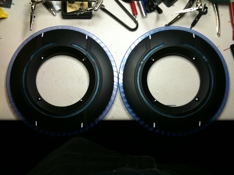
Here's a layout of the two halves:
Front Half:
All LEDs
LED Driver
Netduino Mini
Back Half:
2 Lithium Polymer Batteries
Charge Detection Circuit with charging pads
Toggle switch for main power
Momentary switch for animation changes
Toggle switch for mode changes (SPDT On-On Switch)
External connector for Programming interface
Connections between the two halves (connections are made near the momentary button):
1: Primary interface (minimum connection required to operate the disc)
Momentary Button +
Momentary button -
Ground
Main Power
vDetect
2: Programming Interface
DTR
RX
TX
Ground
There is probably going to be one additional connection as a result of adding that small toggle switch for the mode changes. I need to provide a 5V source (the source for 5V comes from the Netduino mini board) and the two signaling lines for the switch.
I'm going to hold off doing any soldering on the charger circuit until I get my new soldering iron. I've had it with the Radio Shack specials I keep buying, so I invested in a better quality soldering iron that should last quite a bit longer. The iron I'm getting is a Hakko 936.
Edit: posted 3 more pictures from my recent work. Set the charging pins for the charging circuit in place during lunch today. They look rough, but they work, I tested the continuity with my multimeter so they should provide a charge.

 .
. .
.