ByteMaster's Content
There have been 72 items by ByteMaster (Search limited from 06-July 24)
#28200 TechEd 2012
 Posted by
on 27 April 2012 - 12:16 PM
in
General Discussion
Posted by
on 27 April 2012 - 12:16 PM
in
General Discussion
#28961 STM8S and SPI to Mini - Help Request
Posted by
on 13 May 2012 - 05:13 PM
in
Netduino Go
Make sure that you're using the proper "alternate function" that SPI_SS needs. This setting is usually set with the fuses in the third tab of the ST Visual Programmer.
Chris
Thanks Chris, this one costed me at least two hours

On the STMS8S103K3 (32 pin) all the fuses were set properly to have SPI work out of the box. If you are working with the STM8S103F3 (20 pin) you need to set AFR1 = Port A3 Alternative Function = SPI_NSS, Port D .....
#29034 STM8S and SPI to Mini - Help Request
Posted by
on 14 May 2012 - 06:02 PM
in
Netduino Go
Do you need high data rates on any of these modules?
Not sure on that yet, I suspect I'll go through a few propellers, but hopefully not a lot of fingers figuring that out. My plan is to do the time critical stuff on the STM chips and then send the processed data back to GO! to let it figure out where to hand if off to do the actual control. So I envision lots of really small packets via SPI, I ?think? that will be adequate.
#28969 STM8S and SPI to Mini - Help Request
Posted by
on 13 May 2012 - 08:53 PM
in
Netduino Go
ByteMaster--now you have me curious, wondering what you're building

Glad this is up and running for you now. If you need anything else, just holler...there's lots of experience and expertise in the community.
Chris
Hi Chris - yeah, I wish I would have posted this question a while ago
 I've learned a lot from just going through the forums and reviewing some of the beginnings of what's in the Wiki. As I get more into this I'll start adding some stuff that I've learned.
Well my master plan [insert evil laugh emoticon] is to build a Quad Copter off of the Netduino GO! platform. I started off with a standard netduino and it seemed like I'd be pushing it too hard for the update rates I was looking for. So next I started building some AVR based modules to hang off of the first generation Netduino. Needless to say once you guys introduced the GO! platform my plans did a 180 and started to fall in love with the STM chips and for a lack of a better term an "object-oriented" way of building embedded apps.
Anyway here's my current effort that my wife is getting jealous of all the attention I'm giving it as I'm trying to stumble through putting it together:

Top right is a a GPS module based upon the Wi2Wi chip, this one is getting close, I just need to finish up the SPI dance between the STM & GO! This also as a 256K serial EEPROM for logging location data.
Then a module for either an XBee or a RN-XV Wifi device using an STM8S100F3 to do the buffering and communications to GO! via SPI. Eventually my plan is to just get the SMD chip version of the RN-VX this.
Third down is an RTC module based on the PCF8523 chip...it looks sort of dead without any LEDs but the I2C stuff is working so I just need to tie it back to GO!
Finally the two boards not populated, the one on the top is a simple GPIO board with ADC, PWM, etc.. and the one on the bottom will be my IMU board with a Gyro, Compass/Accelerometer and pressure sensors as well as an EEPROM.
Then of course we have the beautiful LCD Touch Module from NWazet and a few button modules to help with the testing.
I'm on vacation this week so I hope to flush out the hardware and then get some real boards on order from Seeed. Once I do so and if anyone is interested, I'd love to get some help with coding some of this stuff up! I'm not really in a position to do manufacturing of this stuff but I'm certainly going to release these as Open H/W S/W as well as a few blog posts on what I've learned.
Then sometime this summer when the firmware is done, the plan is to build Windows Phone and Windows 8 apps to act as the flight controller. Back in my comfort zone

One thing I did find incredibly helpful on when testing this stuff was getting a few of these extenders from GHI, they work really good to tie into the signals to and from the GO! board.

http://www.ghielectr...log/product/273
Anyway, once I get a little further I'll look at adding some stuff on the Wiki.
-twb
#28976 STM8S and SPI to Mini - Help Request
Posted by
on 13 May 2012 - 10:07 PM
in
Netduino Go
That looks great - especially the home-etched boards. That's just the sort of stuff I want to do - once I've finished with a non-Microcontroller project I'm in the middle of.
Yup - it really is a lot of fun. Creating these boards and "plopping" the SMD parts on top of it isn't nearly as hard as it looks. A relatively cheap stereoscopic microscope and a somewhat steady hand is all you need. Definately give it a try!
#29260 STM8/SPI Chip Select & Interrupt
Posted by
on 16 May 2012 - 01:07 PM
in
Netduino Go
To your primary question:
Could you please provide more details on why you'd like to get rid of the payload size in the message?
I guess more than anything the primary reason is it's just an extra one or two bytes that get sent that are probably not necessary. But as Matt said earlier in the conversation, this is really just temporary until we get a more standardized approach so what's a few extra micro seconds/clock cycles to simplify things. I guess my original vision was some sort of State Machine on both ends that just read in a byte (or handled an interrupt), and depending on what state and figure out what to do with it.
You did bring up a good point though
you'd probably need to handle the situation when the frame transmission is interrupted (for any reason) and the module does not receive complete frame.
I know my module code "libraries" will send a frame as a transaction, but really don't know enough about NETMF to know if some other higher priority interrupt could come in and suspend my modules SPI transmission. Right now I'm feeling very much overwhelmed by the stuff
Thanks again -
Kevin...
#29365 STM8/SPI Chip Select & Interrupt
Posted by
on 18 May 2012 - 01:36 PM
in
Netduino Go
One option is to enable interrupts for the actual pin that you are using as the SPI CS input (rather than using any SPI-specific interrupt). For example, you could enable a rising interrupt for pin A3 (if that is the pin you are using for SPI CS) and process the incoming message in the interrupt handler for that pin.
Ok - coming off of vacation mode...I think I finally understand this direction and what Chris suggested. So basically configure SPI to use Software NSS Management or the SPI_NSS_SOFT option in SPI_Init.
SPI_Init(SPI_FIRSTBIT_MSB, SPI_BAUDRATEPRESCALER_2, SPI_MODE_SLAVE, SPI_CLOCKPOLARITY_LOW, SPI_CLOCKPHASE_2EDGE, SPI_DATADIRECTION_2LINES_FULLDUPLEX, SPI_NSS_SOFT, 0x07);
Then configure the input pin that was originally configured for hardware SS as just a GPIO interrupt;
	GPIO_Init(NSS_PORT, NSS_PIN, GPIO_MODE_IN_FL_IT);

	EXTI_SetExtIntSensitivity(EXTI_PORT_GPIOA, EXTI_SENSITIVITY_RISE_FALL);
Then in the interrupt handler do something like
INTERRUPT_HANDLER(EXTI_PORTA_IRQHandler, 3)
{
	if(GPIO_ReadInputPin(GPIOA, GPIO_PIN_3) == SET)
		GO_SS_Released();
	else
		GO_SS_Asserted();
}
to determine when the transmission starts and ends. Got it...this is exactly what I was looking for.
This still brings up CW2's point:
If you want to have reliable communication, you'd probably need to handle the situation when the frame transmission is interrupted (for any reason) and the module does not receive complete frame.
As I mentioned earlier, not knowing about the NETMF internals, is there a case where a higher priority interrupt could come in and suspend the SPI transition from the Master? I think when checking the CRC byte at the end of the message, I know if it's a valid message or not. Maybe implement some ACK/NAK handshaking. Seems like it's starting to get a bit complex/chatty though

Kevin...
#29258 STM8/SPI Chip Select & Interrupt
Posted by
on 16 May 2012 - 12:48 PM
in
Netduino Go
If you use it in software mode, you can use an interrupt on the line to enable SPI receive mode...and then trap the select line's deassertion to know that you've been deselected. That's most likely how we'll be doing things with the generic firmware, since the SS line gives us a good synchronization strategy.
Chris
Interesting...I never considered looking at the software mode, I think I'll have to read up on that this afternoon. I think I see where you are going with this.
Thanks
Kevin...
#29228 STM8/SPI Chip Select & Interrupt
Posted by
on 15 May 2012 - 09:25 PM
in
Netduino Go
 , I want to get a couple of modules running with the GO! platform. It sounds like the standard firmware might not be released in the immediate future so I'm hacking my own communications layer as a temporary measure.
What I'd like to do is write something that streams some bytes via SPI from the GO! bus into the STM8 and put those into a buffer. Then when the GO! bus is done sending bytes, I want to call a method to figure out what to do with the buffer. The message could be of variable length. It would seem like when the GO bus releases the chip select line, the communications is done and I can hand off that byte array. From looking at the STM docs it doesn't seem like there is any sort of interrupt that can be handled when the chip select line is released, hopefully I'm wrong? Also if there is any other way of using something in the STM to let me know the SPI exchange is done I'd gladly change my strategy. Right now I'm including the payload length in the message, but I'd like to get rid of that.
Any thoughts?!?!?!?!
Kevin...
Sorry if this isn't the right channel for asking these sorts of questions, but it seems like the most appropriate.
Maybe we need a Netduino Stack Exchange Site
, I want to get a couple of modules running with the GO! platform. It sounds like the standard firmware might not be released in the immediate future so I'm hacking my own communications layer as a temporary measure.
What I'd like to do is write something that streams some bytes via SPI from the GO! bus into the STM8 and put those into a buffer. Then when the GO! bus is done sending bytes, I want to call a method to figure out what to do with the buffer. The message could be of variable length. It would seem like when the GO bus releases the chip select line, the communications is done and I can hand off that byte array. From looking at the STM docs it doesn't seem like there is any sort of interrupt that can be handled when the chip select line is released, hopefully I'm wrong? Also if there is any other way of using something in the STM to let me know the SPI exchange is done I'd gladly change my strategy. Right now I'm including the payload length in the message, but I'd like to get rid of that.
Any thoughts?!?!?!?!
Kevin...
Sorry if this isn't the right channel for asking these sorts of questions, but it seems like the most appropriate.
Maybe we need a Netduino Stack Exchange Site 
#29257 STM8/SPI Chip Select & Interrupt
Posted by
on 16 May 2012 - 12:46 PM
in
Netduino Go
One option is to enable interrupts for the actual pin that you are using as the SPI CS input (rather than using any SPI-specific interrupt). For example, you could enable a rising interrupt for pin A3 (if that is the pin you are using for SPI CS) and process the incoming message in the interrupt handler for that pin.
I had thought I read somewhere in the STM8 programming manual that if a pin was configured for an alternative purpose, it could contribute to an external interrupt. I guess I could be wrong and it wouldn't be too difficult to test it.
Even if we can't use it in an external interrupt, there are usually a couple other unused pins on the device, one of which I could tie to the "Slave Select"/SS line rather than "Chip Select"/CS as I called it.
I'm fairly certain some of my messages will be more than 18 bytes and some considerably less. I guess when the chip is running at 16MHz with a fast SPI bus it might not be a big deal. Just trying to be as efficient as possible.Currently, with the RGB LED and potentiometer modules, all SPI messages are 18 bytes long, with the last byte being the computed CRC8 value for the message. So an alternative to monitoring the SPI CS pin would be to process each incoming message after receiving the 18th byte (as long as that byte contains a valid CRC).
Good Point!Much of the protocol will be changing once the official generic firmware is released, so it's probably not worth worrying too much about the details of your protocol at this point. Either of these methods should work for now, and you'll be able to update your module's firmware to work with the new protocol in the future (as long as it follows the recommended electrical specifications).
Matt
Thanks!
Kevin...
#29454 STM8 and Reflashing App
Posted by
on 21 May 2012 - 01:05 AM
in
Netduino Go
#29474 STM8 and Reflashing App
Posted by
on 21 May 2012 - 01:15 PM
in
Netduino Go
I often have ST-LINK/V2 connected through a different socket, wires directly plugged into the IDC cable header, I call it "a poor-man's SWIM adapter"
CW2 - Got-it...pretty cool!
Using a different socket, I assume you couldn't have another STM8 on the same side of the GO!BUS, correct? Or unless I'm missing something, you would end up programming two devices
or at least get some serious issues with both chips on the SWIM line.Hmmm...I'll bet you could also use the break out board that I'm using to connect to the logic analyzer, between the main board and the module, and hookup the ST-Link V2 up to that. This would allow us to leave the programming connector off our module! Way kewl!
Might be worth it to get some boards made up similar to...
...but with a socket to plug in the ST-Link V2. Would be a really good way to do development. All sorts of pins to connect a logic analyzer as well as program the device. In this case, you wouldn't tie those lines back to the main board and could have multiple STM8's without having to worry about bus contention.
Great H/W design here on the GO!Bus!!!
Kevin...
#29470 STM8 and Reflashing App
Posted by
on 21 May 2012 - 10:58 AM
in
Netduino Go
This wiki page details most of the hardware/electrical requirements for STM8S-based modules:
http://wiki.netduino...ders-Guide.ashx
This looks like a great asset!
Pin 4 should be connected to SWIM and pin 5 should be connected to NRST
We probably have to assume that those lines are not Hi-Z, so durring development with the ST-Link2 attached, they should be disconnected? I guess a good approach would be cutting those lines in the 10 pin ribbon cable.
Kevin...
#29036 Standard STM Library for GO!
Posted by
on 14 May 2012 - 06:09 PM
in
Netduino Go
#32914 SPI/I2C Conflict
Posted by
on 30 July 2012 - 09:04 PM
in
Netduino Go
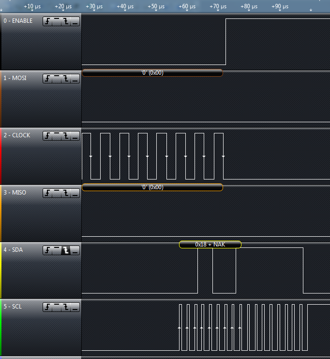
I have sensor board where I'm pulling I2C data from a gyro every 10ms, I'm then triggering an IRQ to the GO! board for the GO! board to pull the data via SPI. Most of the time this works great. The challenge is when GO! board is busy and doesn't get around to handling the IRQ for a while and does so when the module is pulling the next data from the gyro. When this happens it appears as if the I2C line will ignore setting the stop condition and my gryo jumps the tracks and kills the I2C bus by keeping the line low.
The SPI communication is done via an interrupt handler and the I2C is initiated by a GPIO IRQ, but just bangs out the I2C communcication sequentially (doesn't use an IRQ). I did set the GPIO IRQ priority lower so it wouldn't interfere with the SPI communcations.
Here is the offending I2C code, note that TWB_GO_GetState() is used to determine if SPI communications is occurring. If so we just spin until we go back into an idle state.
	while(_rxBytesToReceive > 0) {
		if(TWB_GO_GetState() != GO_STATE_Idle) {
			TWB_Sleep(1);
		}
		else{
			if (_rxBytesToReceive == 1){
				/* Disable Acknowledgement */
				I2C_AcknowledgeConfig(I2C_ACK_NONE);

				/* Send STOP Condition */
				I2C_GenerateSTOP(ENABLE);

				/* Poll on RxNE Flag */
				while ((I2C_GetFlagStatus(I2C_FLAG_RXNOTEMPTY) == RESET));
				//while (I2C_GetFlagStatus( I2C_FLAG_TRANSFERFINISHED) == RESET) {}

				/* Read a byte from the Slave */
				_rxBuffer[_rxBufferIdx++] = I2C_ReceiveData();

				/* Decrement the read bytes counter */
				_rxBytesToReceive--;
			}
			else if (I2C_CheckEvent(I2C_EVENT_MASTER_BYTE_RECEIVED) ){
				/* Read a byte from the I2C Bus and stuff it in the buffer*/
				_rxBuffer[_rxBufferIdx++] = I2C_ReceiveData();

				/* Decrement the read bytes counter */
				_rxBytesToReceive--;
			}
		}
I know from my logic analyzer that the code with one byte left runs, and blocks on the SPI being active (can tell by the NAK). If you look at the attached capture from the logic analyzer, you can see the I2C lines are low until the SPI communication is done, then you can see the I2C line clocks in the last byte and sends a NAK. The problem is it doesn't send the stop condition after the NAK, it looks like it want's to clock in another byte and this apparently is confusing the heck out of the gyro.
Did that make any sense at all?!?!?!?
Help!
Attached Thumbnails
#30141 SetSocketPowerState
Posted by
on 03 June 2012 - 05:33 PM
in
Netduino Go
#33186 SetSocketPowerState
Posted by
on 06 August 2012 - 10:57 PM
in
Netduino Go
What scenario(s) would this feature be useful to you? We're working on an update to the mainboard and GoBus assembly...so any/all feedback and requests are very timely.
Any updates on this? I see the API in place for SetSocketPower and would really love to take advantage of this for failure recovery. Any work around you can think of with the current version? Is the source available for GoBus.dll? Could the update be made there to allow this to work?
-twb
#30172 SetSocketPowerState
Posted by
on 04 June 2012 - 12:26 PM
in
Netduino Go
What scenario(s) would this feature be useful to you? We're working on an update to the mainboard and GoBus assembly...so any/all feedback and requests are very timely.
I can think of two scenarios where this might be useful:
1) From a module builders perspective, if my module starts behaving badly it would be nice to toggle power to do a full reset. In some case it would be nice to toggle power to the module to reset peripheral chips in addition to just resetting the uC.
2) From a app perspective, in some cases it might be nice to shut down unused modules to save power
Kevin…
#47079 SainSmart 16x2 (1602) LCD Keypad Shield on Netduino?
Posted by
on 12 March 2013 - 01:04 PM
in
General Discussion
It should, with the Hd44780Lcd class.
Since the Netduino Plus 2 is so blazingly fast, if you attempt to use this class as-is it will won't work.
What you will need to do is hold the clock enable pin high just a little longer rather than just toggling it as was done in the original driver.
This happens around line 366 in the _Write4Bits method of Hd44780Lcd.cs.
private void _Write4Bits(byte Byte){ ....... // Enables the pin for a moment this._CePin.Write(true); for (var idx = 0; idx < 1000; ++idx) ; this._CePin.Write(false);?
?
?
?
?
?
I haven't experimented too much with the exact number of iterations necessary but 1000 seemed to do the trick.
To deploy this you can either update the source code in the tool box and recompile, or just include the file Hd4470Lcd.cs into your project and make the change there. Either way you'll need to include references for "Toolbox.NETMF.Core" and "Toolbox.NETMF.Hardware.Core" to your project.
-twb
#33542 NiVek GO! QC1
Posted by
on 13 August 2012 - 07:34 PM
in
Netduino Go
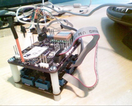
I've done a full writeup on my blog The Wolf Bytes and my plan is to do a full series of all the "stuff" H/W and S/W that goes into this as blog posts. When I have some faily major progress I'll update this topic and if anyone has any questions on how this stuff works, please ask them here or send me an email at kevinw@software-logistics.com. My plan is eventually to release all the H/W and S/W as open source, but I'm also considering some alternatives to sell kits, at least for the electronics.
Thanks to Steve Bulgin (beter known as Gutworks) I was able to figure out how to post a quick and dirty video (read as: one take and no editing) to the forum.
In addition, I've attached a picture of the piggy-back board for the GO! main board that contains a few STM8S207's that power the sensors and the flight controls.
Enjoy!
-twb
Attached Thumbnails
#33545 NiVek GO! QC1
Posted by
on 13 August 2012 - 07:48 PM
in
Netduino Go
Oh, I see why you made your board that size
Yeah, turned out kinda cool! I'm working on a design that has female connectors on the bottom of the board so it can "snap on" (of course it would sill be mechanically attached). Any "challenges" you see w/ that?
Really need CW2's STM8 reflashing app to make that one happen though (hint, hint
)-twb
#28970 [nwazet Go! modules - update announcements
Posted by
on 13 May 2012 - 09:12 PM
in
Netduino Go
#28979 [nwazet Go! modules - update announcements
Posted by
on 13 May 2012 - 11:21 PM
in
Netduino Go
Now that wouldn't be hacking now, would it?
...Or, you could just wait for Chris' firmware flashing application
I hope this helps.
Cheers,
-Fabien.

Thanks for the detailed write-up Fabien!
#29333 [nwazet Go! modules - update announcements
Posted by
on 17 May 2012 - 01:05 PM
in
Netduino Go
Hi Kevin,
I have a solution for you to get out of "Flashlight Mode"
That's it.
- Connect STLinkv2 to your PC
- Start STVP and configure it for the STM32F205xE chip
- Load the .hex version of the Touch Display firmware from the repository here (I just added it for you)
- Make sure you're on the "Program Memory" tab in STVP and hit CTRL+P (program current tab / active sectors)
Let me know how it goes.
Cheers,
-Fabien.

Simple enough - uploaded the bits to the device and I'm back in business, I'm very much looking forward to playing with the non-blocking touch features later today -
Thanks Fabien!
Kevin...
#29298 [nwazet Go! modules - update announcements
Posted by
on 16 May 2012 - 09:57 PM
in
Netduino Go
Another method is to solder a 10 position FCI connector to the un-populated JTAG pads on the back of the Touch Display module and flashing the module using STLink-v2 from your favorite compiler from the firmware's source code or using ST's DFU utility using the binary version of the firmware.
Anyway, I took your advice, soldered the connector on the back of the board and have ST Visual Programmer chatting with my display board. Now I just need to get the bits on it. I tried opening the project in IAR Workbench, but got an ARM Toolchain error followed by an invalid project. Converting to run w/ ST Visual Develop (the tool I use right now) seems like it might be a bit more of a challenge then I'm ready for with my current lack of knowledge

So I was able to open and convert the file from the BIN format, to the DFU format and then back to a S19 and HEX format. When I opened these files in STVP, it looks like the 8000000 offset disappeared and I received a "Out of range" message and nothing loaded.
I know this is beyound the "call-of-duty" for the display module support, but any chance you can point me in the direction to get the 1's and 0's from the BIN file onto the metal?
Also if there is anything else I can do to help troubleshoot this effort, I have Chris's flashing software along with the ST-Link2 ready to try "stuff". Let me know.
Thanks
Kevin...


