Posted by
I recently took up a high-tech form of biking by modifying the bicycle collecting dust in the garage with an e-bike kit (to help get my lard butt up the hills!).
Being a computer software geek my next thought was to create an E-Bike computer using a netduino that I had on hand.
The project has some significant goals that require a custom shield to interface with the bike and peripherals that I wanted for my over-all feature set.
In the process of working on this I went down many blind alleys given my project goals.
There are many PCB cad programs out there for use. Some proprietary in the aspect they make it easy to design but then lock you into ordering boards only though them, and others that output common formats that allow you to order from any board house.
Since the goal was to produce a shield I started with the Fritzing project. At the time of writing this it’s a fairly nice starter design tool if you are dealing with older style through-hole components that you can use on a bread board.
http://fritzing.org/
The main attraction to me for using this tool is that it has a simple order button and you could get your custom PCB for about $20.00. So not much financial risk in knocking out a quick design; verses roughly eight to ten times the cost for other firms offering the proprietary tools.
As I come to learn foot prints and mechanical layout that area of functionality is the major hurtle with any PCB CAD product if it is not in its default libraries.
The downside of Fritzing comes in when you shift to surface mount parts as it has limited foot print support, I spent an extreme amount of time just trying to get the foot prints for the IC’s that I wanted to use right.
Once I had the foot prints right I then spent lots more time wrestling with the primitive auto routing that this tool supports and its design rules checking. It really doesn’t handle Via’s well, they are frustrating to work with and can’t be easily moved as they are locked in place.
This may improve with future releases.
After growing frustrated with the limitations of this tool, I then tried a few other PCB cad programs before settling on the free version of DipTrace which has an extensive foot print library and actual modern library of main stream components.
Most of the components I wanted to use were already supported by DipTrace, yeah!
The free version of DipTrace limits a project to 300 pins which is generally more then you will need for a any shield project.
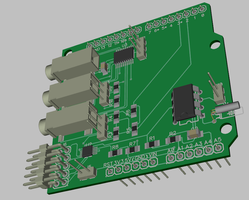
And hey it will build you a 3d view of your board with components as you see in this post above.
Building an Arduino shield board means first coming up with the actual physical board layout, something that is built into the Fritzing solution.
Turns out the Arduino shield is not exactly laid out on a standard grid and the actual dimensions were difficult for me to find.
I was able to find a DipTrace Arduino project on github that gave me a major leg up on getting started.
Check out the rocketscream reflow oven controller project.
Once I switched to DipTrace I spent much less time wrestling with the tool and more time creating and rethinking my solution.
While I am not finished creating my project and I may in fact move away from using a shield, I think my current efforts makes a great starting point for others!
Things you need to download:
http://www.diptrace.com/download.php Get the DipTrace FreeWare beta and the 3D models (beta has more predefinded parts in its library)
http://sourceforge.n...title=Main_Page FreeCAD program which you will need for converting manufactures 3D models of their parts to STL format.
http://www.wings3d.com The Wings3D conversion program that you will use to convert from the STL 3D format into the VRML 2.0 format that DipTrace uses for their 3D part models.
http://freewrl.sourc....net/index.html Viewer that allows you to visualize VRML 3D models of existing parts.
Videos you will wish to watch to get you started
http://www.diptrace.com/tour/ DipTrace’s guided video tour
Basic procedure to take a 3D part and convert it for use with DipTrace using FreeCad and Wings3d to the VRML 2.0 format required by DipTrace.
http://www.veengle.c...STP Import.html View the fifth video on this page “Import STEP file” on how to take a more common STEP format for a 3D part and export it as a STL file. Hint when starting FreeCAD immediately select a mesh project type, before importing the STEP 3d model!
How to take physical parts like headers and connectors from 3DCentral into DipTrace.
http://youtu.be/bIiXPo-vnRA Third party explanation of components and pattern libraries, fill in a lot of holes for me.
Web Pages to view on getting your PCB design fabricated
http://digital-diy.c...a-osh-park.html
http://dorkbotpdx.org/wiki/pcb_order
http://digital-diy.c...on-sources.html
http://www.lucadente...studio/?lang=en
https://batchpcb.com/news
Attachments to this post
Attached are two zip files which you extract to your DipTrace folder that is created under My Documents after you run DipTrace for the first time. The librarys zip file has the rocketscream library and a library that I created for the CUI audio jack, plus 3d images for the headers that I make use of.
The projects zip file has my project that existed at the time at the time I wrote this post and a base board starter project. My project would be good to play with as you modify the schematic design, move components around on the PCB and experiment with the auto routing.
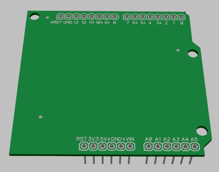
The base board starter has been cut down from the rocketscream project and has updates for the 3D header pins.
Note these files make reference to my personal development path so you will need to change the reference path to the libraries if you make changes to reflect the actual path on your system.
I hope people find this of use, oh and by the way here's a picture of the board in the base board starter project.
Enjoy
Fred
PS. I am no way an expert with DipTrace and make no claims to technical accuracy of the included content; so please read their forums for help! I also have not produced a physical board, just going though the learning curve myself, so please take this post in the spirit it was intended.
Attached Files
-
 My Libraries.zip 532.71KB
354 downloads
My Libraries.zip 532.71KB
354 downloads
-
Projects.zip 36.69KB
293 downloads