hoquet's Content
There have been 12 items by hoquet (Search limited from 16-July 24)
#33488 Netduino Go with Xbee module not supported yet?
 Posted by
on 12 August 2012 - 04:53 PM
in
Netduino Go
Posted by
on 12 August 2012 - 04:53 PM
in
Netduino Go
#33398 Netduino Go with Xbee module not supported yet?
Posted by
on 11 August 2012 - 02:05 AM
in
Netduino Go
The XBee Gadgeteer is plugged into Socket 1. I Have the Go Button plugged into Socket 5. Nothing else is plugged into any other socket.
Here is the code on the NDG side:
                serialPort = new SerialPort("COM1", 9600, Parity.None, 8, StopBits.One);
                serialPort.ReadTimeout = 500;
                serialPort.WriteTimeout = 500;
                serialPort.Handshake = Handshake.None;
                serialPort.DataReceived += new SerialDataReceivedEventHandler(serialPort_Datareceived);
                serialPort.Open();

        private static void serialPort_Datareceived(object sender, SerialDataReceivedEventArgs e)
        {
            SerialPort spL = (SerialPort)sender;
            Debug.Print("Data Received");
        }
        static void button_ButtonReleased(object sender, bool buttonState)
        {
            Debug.Print("Button Pressed");
            string output = " Hello from your Netduino: ";
            byte[] bytes = System.Text.Encoding.UTF8.GetBytes(output);
            serialPort.Write(bytes, 0, bytes.Length);
        }
On the windows form side I am able to receive the data from the NDG, but when I send data, I see the Gadgeteer light go on, however the event is not fired.
Here is the code on the windows form side.
            serialPort = new SerialPort("COM3", 9600, Parity.None, 8, StopBits.One);
            serialPort.ReadTimeout = 500;
            serialPort.Handshake = Handshake.None;
            serialPort.DataReceived += new SerialDataReceivedEventHandler(serialPort_Datareceived);
            serialPort.Open();

        private void button1_Click(object sender, EventArgs e)
        {
            // then we will prepare sending the message
            byte[] buffer = new byte[MOVEMESSAGE.Length];
            // convert the string to bytes
            buffer = System.Text.Encoding.UTF8.GetBytes(MOVEMESSAGE);
            // write it to Xbee through serial
            if (!serialPort.IsOpen) { serialPort.Open(); }
            serialPort.Write(buffer, 0, buffer.Length);
        }
        private void  serialPort_Datareceived(object sender, SerialDataReceivedEventArgs e)
        {
            SerialPort spL = (SerialPort)sender;
            txtBox1.Text += "Data Received";
        }
The confusing part is that I can send from the NDG and receive on the windows form, but I cannot send from the windows form and receive on the NDG. However when I switch the XBee's, I can send from the windows form and receive on the NDG. But I cannot send from the NDG anymore and receive on the windows form.
Thanks
#33350 Netduino Go with Xbee module not supported yet?
Posted by
on 10 August 2012 - 04:19 AM
in
Netduino Go
#33179 Netduino Go with Xbee module not supported yet?
Posted by
on 06 August 2012 - 08:45 PM
in
Netduino Go
 Thanks
#33139 "Preparing to deploy..." takes ages
Posted by
on 05 August 2012 - 08:18 PM
in
Visual Studio
#33025 Netduino Go with Xbee module not supported yet?
Posted by
on 02 August 2012 - 04:56 PM
in
Netduino Go
#32995 Netduino Go with Xbee module not supported yet?
Posted by
on 02 August 2012 - 02:07 AM
in
Netduino Go
#32678 Powering the Netduino Go! with a Lipo
Posted by
on 26 July 2012 - 02:20 AM
in
Netduino Go
#32633 Netduino Go with MMA7361 Accelerometer
Posted by
on 24 July 2012 - 04:11 PM
in
Netduino Go
It seems if I skip the voltage calculation and go straight to the g calculation, then convert to angle, I get quite a bit of difference in the angle of x, y, z.
With the voltage step and offsets, I get the following on angles:
X: 0.041974933800873783 Y: -0.41450604992784712 Z: 65.376588015735521
X: -0.59290646870709129 Y: 0.50895272001477965 Z: 62.864042500339835
X: -1.7474773687631002 Y: -1.107157680696504 Z: 63.763641727439321
X: -0.30431967368129509 Y: 0.39351806301346776 Z: 63.503725175255653
X: 0.44598813546831534 Y: -0.29907273468431761 Z: 63.763641727439321
X: -0.65062539850273071 Y: -0.010493732570229987 Z: 63.763641727439321
X: -0.015740598965353455 Y: 0.22036892606078706 Z: 62.864042500339835
X: 0.15740618567488954 Y: 0.047221801648020693 Z: 62.990856852350745
Without the voltage step and offsets and using 6.0g instead of 3, I get the following:
X: -2.8975050412313226 Y: 7.9588318815438672 Z: 90
X: -2.8975050412313226 Y: 9.6579297791642684 Z: 74.444248900961227
X: -2.8134508092914667 Y: 9.0623482723407758 Z: 90
X: -3.4019678954538319 Y: 10.254566768819068 Z: 82.397076755629371
X: -3.1497059167086494 Y: 10.169265624836738 Z: 85.612598169987365
X: -2.8975050412313226 Y: 10.083987254504757 Z: 80.684933454463348
X: -3.4019678954538319 Y: 7.9588318815438672 Z: 90
Without the voltage step and no offsets and using 3.0g I get the following:
X: -1.5322675849620377 Y: 4.7275420628731126 Z: 30.242639723333181
X: -1.6582412247915879 Y: 4.4327759196193295 Z: 29.275597460743235
X: -1.7842228834621141 Y: 4.6433107105722939 Z: 29.951543350138909
X: -2.0362127006474937 Y: 5.0645717506580912 Z: 28.795508763249902
X: -1.6162491506822376 Y: 4.7696615680989565 Z: 29.516487394448284
X: -1.3643141506658361 Y: 5.106712577007734 Z: 28.891348373149537
X: -1.7002341898803937 Y: 5.0645717506580912 Z: 29.323729867577644
First, I don't think I should be converting Z to an angle since it is the measure of gravity. The XL does have multiple settings to be able to switch it to 6g instead of 1.5g. I can change it, but I'm running out of digital ports. I am using most of the digital ports for the lcd.
Noob question:
How do I get more digital I/O ports?
Thanks
#32313 Netduino Go with MMA7361 Accelerometer
Posted by
on 20 July 2012 - 02:16 AM
in
Netduino Go
#32252 Netduino Go with MMA7361 Accelerometer
Posted by
on 19 July 2012 - 04:40 AM
in
Netduino Go
I may have figured out what the values are that I am reading. I was looking for what analoginput.read was actually reading. I tried finding the information on the MMA7361 chip. After some time, I finally came across a good article about NETMF Analog input vs Microsoft SPOT http://www.tinyclr.c...m/topic?id=7832
The value I should see from a 12-bit Shield from the NetDuino Go performing analogInput.read() should be between 0 and 1 for 3.3v. The post helped. Anyways, from there I found an article on someone converting analog input to read values to degrees. http://www.dfrobot.c...1_(SKU:_DFR0143)
I understand most of the code, except for why they are subtracking 1.62, 1.74, and 1.48 from the voltage.
            // read the converted value from the sensor... this returns a double
            // between 0 (0V) and 1 (3.3V)
            analog_x = accX.Read();
            analog_y = accY.Read();
            analog_z = accZ.Read();

            // now, if we want, we can calculate the number of volts by multiplying
            // the converted value by 3.3
            vol_x = analog_x * 3.3;//convert analog_x-->voltage value(v)
            vol_y = analog_y * 3.3;
            vol_z = analog_z * 3.3;

            //range x: 0.83 - 2.41 1.62
            // y: 0.96 - 2.53 1.74
            // z: 0.72 - 2.23 1.48

            add_x = vol_x - 1.62;//calculate the added x axis voltage value
            add_y = vol_y - 1.74;
            add_z = vol_z - 1.48;

            g_x = add_x / 0.8;//calculate the gram value
            g_y = add_y / 0.8;
            g_z = add_z / 0.8;

            if (g_x <= 1 && g_x >= -1) //We use this condition to prevent the overflow of asin(x).( If x>1 or x<-1, asin(x)=0)
            {
                degree_x = System.Math.Asin(g_x) * 180.0 / System.Math.PI;//calculate the degree value
                degree_y = System.Math.Asin(g_y) * 180.0 / System.Math.PI;
                degree_z = System.Math.Asin(g_z) * 180.0 / System.Math.PI;
            }
            //fix the overflow condition
            if (g_x > 1)
                degree_x = 90;
            if (g_x < -1)
                degree_x = -90;
            if (g_y > 1)
                degree_y = 90;
            if (g_y < -1)
                degree_y = -90;
            if (g_z > 1)
                degree_z = 90;
            if (g_z < -1)
                degree_z = -90;
            //#########################
            //print
Now the output seems a lot more reasonable, when I do tilt the board vertically, the y-axis reads 90. I will do more testing to make sure that it is calculating correctly. I'm excited, I feel like things are working...
Thanks
#32169 Netduino Go with MMA7361 Accelerometer
Posted by
on 18 July 2012 - 05:00 AM
in
Netduino Go
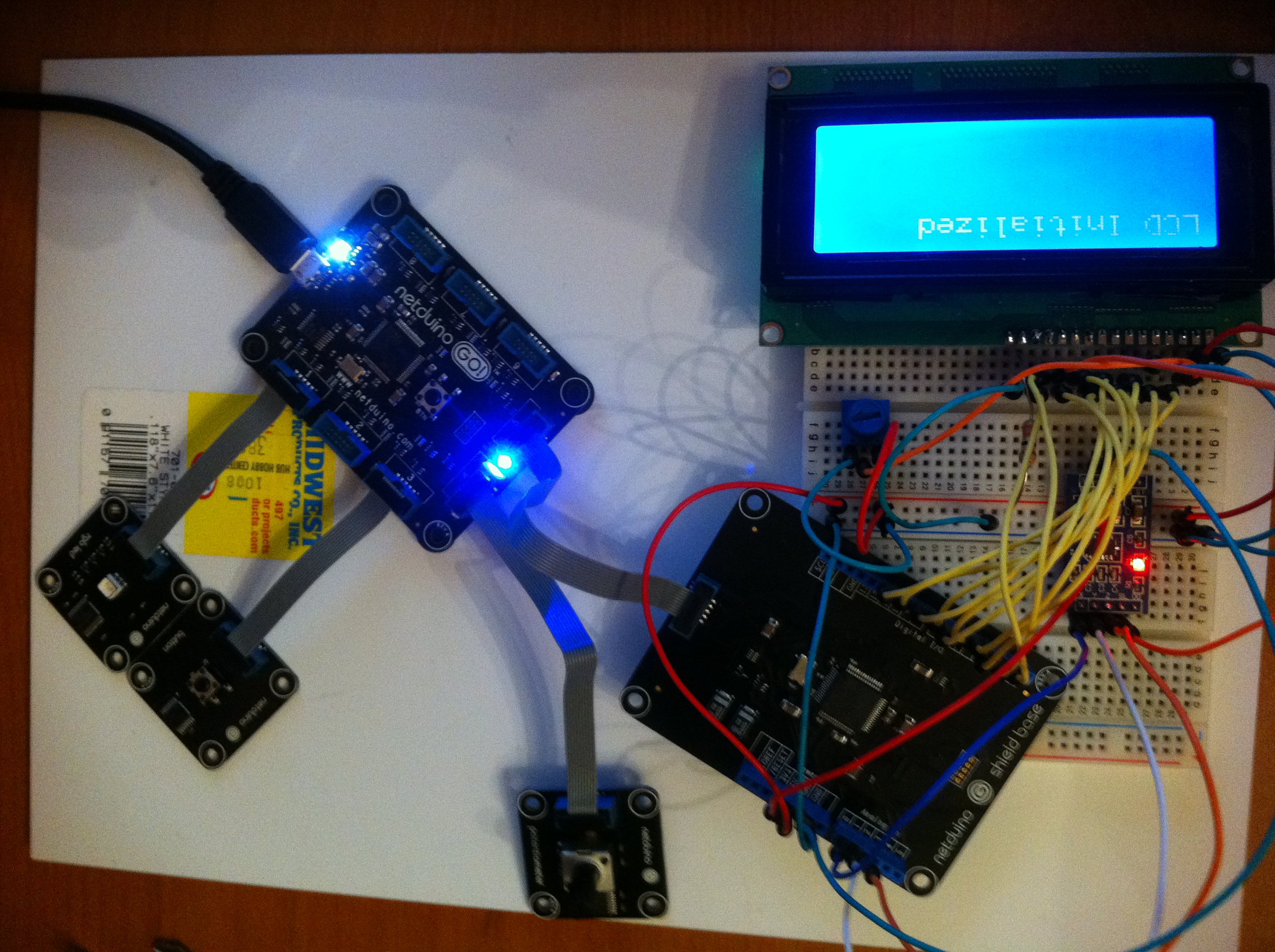
This is my first mini project with the netduinoGo and learning about robotics. I have a programming background, although 10 years ago in .net. I purchased the NetduinoGo starter kit with the button, led, potentiometer, etc.. I got all of it working and was able to make buttons respond, led's blink, etc.. Cool Huh?
I then added the shield base and got that to work. Atleast blink a light and power on. Now I wanted more. So I purchased an LCD, not knowing anything about whether or not it would work or others have used it and if there is some sample code out ther. Then I managed to get an LCD screen connected through various websites and tutuorials. I finally got the Hacktronics LCD Module working with the Netduino. Someone wrote an interface and class along with diagrams on what to connect the digital I/O to the Hacktronics. I can now write out whatever I want to the LCD screen. Although all string manipulations, truncations, etc. I have to handle myself. But it works, I even learned what the heck a resistor is. I also watched a youtube video on how to solder. Hey, it has been 15 years since I took any kind of physics.
Now I thought I would try my hand at an Virtuobotix MMA7361 Accelerometer which I order even before I wrote my first Netduino application. I learned that next time before ordering the hardware, see if there is some code that people have written is readily available for c#. Trying to convert Arduino classes and interfaces is nearly impossible. Anyways, I connected the accelerometer to the shield and followed code that someone else wrote for another accelerometer: Sparkfun ADXL 335
Very basic code:
 // Define our accelerometer inputs
        static AnalogInput accX;
        static AnalogInput accY;
        static AnalogInput accZ;

        public static void Main()
        {
            // Create the Inputs
            accX = new AnalogInput(Pins.GPIO_PIN_A0);
            accY = new AnalogInput(Pins.GPIO_PIN_A1);
            accZ = new AnalogInput(Pins.GPIO_PIN_A2);

            // Keep application alive via loop
            while (true)
            {
                // Read data from the sensor
                double x = (double)(accX.Read());
                double y = (double)(accY.Read());
                double z = (double)(accZ.Read());

                // Output data to screen
                Debug.Print("X: " + x + " Y: " + y + " Z: " + z);
            }
        }
So, what do I get for an output? X: 0.48815628815628814 Y: 0.526984126984127 Z: 0.67252747252747258
X: 0.48815628815628814 Y: 0.5252747252747253 Z: 0.6676434676434676
X: 0.48986568986568985 Y: 0.52722832722832724 Z: 0.66935286935286931
X: 0.49108669108669106 Y: 0.52576312576312578 Z: 0.66984126984126979
X: 0.48888888888888887 Y: 0.52649572649572651 Z: 0.67130647130647125
X: 0.48766788766788766 Y: 0.52747252747252749 Z: 0.66862026862026858
X: 0.48888888888888887 Y: 0.52771672771672773 Z: 0.67057387057387052
X: 0.48840048840048839 Y: 0.52503052503052505 Z: 0.66935286935286931
X: 0.4879120879120879 Y: 0.5252747252747253 Z: 0.67106227106227101
X: 0.48913308913308912 Y: 0.5252747252747253 Z: 0.66788766788766785
X: 0.48717948717948717 Y: 0.52503052503052505 Z: 0.67057387057387052
X: 0.4879120879120879 Y: 0.52551892551892554 Z: 0.66984126984126979
X: 0.49108669108669106 Y: 0.52722832722832724 Z: 0.66862026862026858
.....
Great, seems like it is working. How the heck do I veryify that it works? Even though the device is sitting on my desk at home, the numbers keep changing. I read some articles about getting the g-force, radians, and using offsets. I just want something like degrees tilt in either of the 3 axis with 2 decimal places. Any resources anyone would recommend would be great. I'll keep posting my progress as well as I add a motor shield and the xbee shield. I'm just learning, so please keep it simple. I am also attaching the work that I have done. For the hacktronics LCD which is a 4 line 20 char, I would be happy to share my code and board configuration.
Thanks