CW2's Content - Netduino Forums - Page 2
   
Netduino home hardware projects downloads community

Jump to content


The Netduino forums have been replaced by new forums at community.wildernesslabs.co. This site has been preserved for archival purposes only and the ability to make new accounts or posts has been turned off.

CW2's Content

There have been 148 items by CW2 (Search limited from 11-May 23)


By content type

See this member's


Sort by                Order  

#59372 Control 80V DC Motor/Bulb Using Netduino 2

Posted by CW2 on 24 July 2014 - 07:31 PM in General Discussion

CW2 : Thank you too, but Im very sorry. I'm very new to these things, so half of things you said, just bounced off my head. But yes I'm learning through web sites, as always not easy. :)


There is really no need to apologize. How about this article? (replace Arduino with Netduino, and of course the application code has to be different, but the principle remains the same).


#59380 Control 80V DC Motor/Bulb Using Netduino 2

Posted by CW2 on 25 July 2014 - 07:29 AM in General Discussion

Well, you could use PWM, but for simple on/off control it is easier to start with a digital pin:
 

public static class Program
{
  public static void Main()
  {
    // Motor/Bulb connected to D3
    var motor = new OutputPort(Pins.GPIO_PIN_D3, false); // Initially off

    while(true)
    {
      motor.Write(true);   // On
      Thread.Sleep(500);
      motor.Write(false);  // Off
      Thread.Sleep(500);
    }
  }
}

Technical notes about the RFP30N06LE transistor (datasheet pdf) used in the bildr.org article:

  • It has maximum voltage 60V - enough for 12V bulb, but not enough for 80V motor.
  • It can be controlled directly from Netduino pin, it requires at least 2V gate voltage (Netduino has 3.3V output).
  • It is rated for 30A continuous current, it can switch about 20A at 3.3V gate voltage. You'd need higher gate voltage for higher load current, i.e. another small transistor to control this power MOSFET.


#59382 Control 80V DC Motor/Bulb Using Netduino 2

Posted by CW2 on 25 July 2014 - 08:22 AM in General Discussion

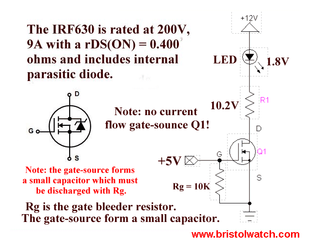
The voltage naming notation is a little bit confusing in the article - just use "GND" (0V) for the black wire and and "+V" (12V .. 80V) for the red one. The transistor in the circuit act as a switch that terminates or connects the load to GND (ignore the voltage numbers in the picture):


tr8.gif


#59367 Control 80V DC Motor/Bulb Using Netduino 2

Posted by CW2 on 24 July 2014 - 12:03 PM in General Discussion

Could you please help, assuming motor is a bulb and DC output is 12V (external, not from netduino).


In this simple scenario, i.e. controlling 12V DC bulb from Netduino, you can use just a transistor switch.


You'd need to calculate the load current IL = P/V, where P is the bulb power rating and V is the voltage, so for example for a small 4W automotive light bulb the current is 4/12 = 0.33 A. Then you select a transistor that can handle such current, preferably a MOSFET. In this particular case of relatively small current, you should be able to find a suitable MOSFET that has 'logic level' control, i.e. gate voltage threshold <3V, so you can control it directly from [3.3V] Netduino pin. Otherwise, you'd need another 'general purpose'/'small signal' transistor (BJT or MOSFET) to control the 'big' power transistor (which typically requires ~10V gate voltage for the rated current).


Regarding the DC motor control: if you only need simple control, i.e. on/off switch, then the 'bulb switch' circuit can be used in the same way, assuming the transistor has appropriate current rating; and it is recommended to add a flyback diode (to handle current spikes generated when motor changes its state). Otherwise, I would consider using a specialized motor driver ("H-Bridge"), as suggested by Mario. (You can use H-Bridge for the bulb too.)


There is a lot of information available on the Internet about how to control a transistor switch from a microcontroller output, including complete circuit schematic, part selection etc.


#59386 Control 80V DC Motor/Bulb Using Netduino 2

Posted by CW2 on 25 July 2014 - 11:50 AM in General Discussion

You cannot switch voltage polarities, you'd need to use different kind of transistor (N-channel vs. P-channel MOSFET).


Technically, you can change values, as long as the difference is the same. Voltage is electrical potential difference between two points, so 0 .. 60V is the same as -60 .. 0V which is the same as 37.2 .. 97.2V (because 60 - 0 = 0 - (-60) = 97.2 - 37.2 = 60V); but switching wires 60 .. 0V is different (0 - 60 = -60V, negative). You can destroy electrical parts with wrong voltage.


If you don't connect Netduino ground and your power supply ground, the circuit most likely will not work (unless there is a common ground connection, for example when you power the Netduino from the same power supply as the motor/bulb).


By moving the resistor, you've completely changed the circuit behavior - previously, the resistor (between gate and ground, "pull-down") ensures safe 'off' state, it means the switch is guaranteed to be off until you set Netduino pin to high. Now, the resistor in series (between Netduino pin and gate) just limits the current - it does not do any harm, but it is also useless, because MOSFET is driven by voltage, not by current (you'd need this resistor for BJT transistor, to limit base current). Additionally, you've lost that 'safe-off' feature, and you could get unexpected behavior, because Netduino pin is in 'floating' (high-impedance) state during startup, until you create the OutputPort instance, thus switching it to digital output mode.


If you really want to understand how the electronic works, have a look at sites like All About Circuits or Electronics Tutorials, they can explain it much better than me :)


#59907 Convert Arduino Library To Netduino

Posted by CW2 on 26 August 2014 - 04:18 PM in General Discussion

Now I am getting a bunch of "the name ______ does not exist in the current context."


Well, those are Arduino library function calls and some constants - the good news is you don't need to convert that, just implement spiTransfer() function to call .NET Micro Framework SPI.Write() method and delete all pinMode(), digitalWrite() etc. calls, which are not needed (because SPI class does that internally; including the ChipSelect pin if you set it in the configuration).


#59914 Convert Arduino Library To Netduino

Posted by CW2 on 27 August 2014 - 07:08 AM in General Discussion

Well, how should I put this... the whole LedControl code is basically one SPI.Write() method call to transfer 16 bit data (spiTransfer() function) to the MAX and a few methods that set the data to perform the desired command.
 
Personally, I would stop converting the Arduino code and start with C# from scratch, using the device datasheet as reference and the Arduino code if in doubt (assumed to be working). There is also possibility that the converted code will not work at the first try, so you'd need to troubleshoot it, and it is much easier to troubleshoot code you understand well (e.g. written yourself).
 
Create a new project and start talking to the MAX using the SPI class, it should be something like this: 

...
public static void Main()
{
  var max = new SPI(new SPI.Configuration(...));
  var data = new byte[2]; // 16 bits (address + 8 bit data)

  // Display test mode
  data[0] = 0x0F; // Address
  data[1] = 0x01; // Test mode on

  max.Write(data);

  Thread.Sleep(Timeout.Infinite);
}

Once you get the code working (written from head, so probably does not even compile, data buffer can be ordered the other way round etc.), you can add command constants and wrapper methods, then you will be able to use the Arduino code because you'll see what it does and where it fits.


#59916 Convert Arduino Library To Netduino

Posted by CW2 on 27 August 2014 - 02:02 PM in General Discussion

Unfortunately, I don't have any MAX7219, but it seems to be fairly easy to operate the cascade:

  • Connect all LOAD/!CS inputs together (to Netduino pin used as SPI CS),
  • Connect MAX DOUT to DIN to chain the devices.
[Netduino] MOSI -> DIN [ Max#1(16 bits)] DOUT -> DIN [Max#2(16 bits)] DOUT -> ...
           CS ------------- LOAD/!CS ------------------- LOAD/!CS

Note: The clock (SPI CLK) signal is omitted for sake of brevity, it must be connected together.

That means the cascade behaves like one N×16 bits register. So, when you send 16 bits to the first Max#1, the contents of its internal 16 bit register is shifted out to the adjacent device, whose contents is shifted out to the adjacent device (if any) etc. (you can connect DOUT to Netduino MISO and you can receive the data back, which is often useful - this way you can detect the number of  chained devices in runtime).
 
To operate the cascade, you simply send N×16 bits of data (N×2 bytes) and control all MAX ICs at once. If any of the 16 bits have address zero, i.e. the NO-OP command, the corresponding MAX does nothing and appears as skipped - which enables you to control only selected device(s).
 

var maxChain = new SPI(new SPI.Configuration(...));
var numberOfDevices = 2;

var data = new byte[numberOfDevices*2];
// Important note: The following order is most likely wrong,
// too lazy to think about it...
data[0] = 0x01; // Max#2 Data
data[1] = 0x0F; // Max#2 Address
data[2] = 0x00; // Max#1 Data
data[3] = 0x00; // Max#1 Address

maxChain.Write(data);


#59870 Convert Arduino Library To Netduino

Posted by CW2 on 24 August 2014 - 03:15 PM in General Discussion

OK, got LedControl.cs to pass compile, except for 12 errors. They are:

Type 'Dome_Controller_Arduino_Port.LedControl' already defines a member called 'LedControl' with the same parameter types


You have left empty function declarations in your C# class - this is valid in C/C++, where you can have empty function declaration (in .h) and then implement in at different place (.cpp), but not allowed in C#. Delete all empty functions at the beginning of the C# file, where you have the class declaration from C++ header.


#59902 Convert Arduino Library To Netduino

Posted by CW2 on 26 August 2014 - 06:32 AM in General Discussion

The name 'B01111110' does not exist in the current context


C# does not support binary literals - you'd have to either define those Bxxx constants like


const byte B01111110 = 0x7E;

const byte B00110000 = 0x30;

...


or use the hex literals directly, i.e. instead of B01111110 write 0x7E.


#57894 Azure Service Bus Connection

Posted by CW2 on 02 May 2014 - 03:18 PM in Visual Basic Support

I'd like to see a good (i.e., not OpenSSL) and light-weight (i.e., not OpenSSL) open source TLS implementation for NETMF boards like the Netduino as well. 


Have you had any chance to evaluate PolarSSL or CyaSSL?


#60200 .NET Micro Framework V4.3 SDK-R2-Beta

Posted by CW2 on 24 September 2014 - 06:10 AM in General Discussion

http://netmf.codeple...ses/view/133285
 
This is an SDK only updated release (e.g. porting kit and firmware don't change). The major highlights are:

  • Updated SDK to support use with Visual Studio 2013 (and experimental support for Visual Studio "14")
  • Split SDK installer from Visual Studio support. The SDK MSI now installs only the tools, and reference assemblies (like the desktop versions). A separate VSIX package installs to each supported version of Visual Studio to complete the installation. VSIX packages are available here, as well as from the Visual Studio Extensions Gallery accessible directly from VS.
  • Since VS integration is on a per version basis, this new model also supports simultaneous installations of multiple VS versions.


#60201 .NET Micro Framework V4.3 SDK-R2-Beta

Posted by CW2 on 24 September 2014 - 06:15 AM in General Discussion

Visual Studio 2013 extensions


#60635 Controlling 2WD Chassis using Motor Driver 1A Dual TB6612FNG

Posted by CW2 on 05 November 2014 - 12:24 PM in Netduino Plus 2 (and Netduino Plus 1)

There is no power supply for the motors - VM is not connected (?)


#60637 Controlling 2WD Chassis using Motor Driver 1A Dual TB6612FNG

Posted by CW2 on 05 November 2014 - 12:57 PM in Netduino Plus 2 (and Netduino Plus 1)

The motor driver IC has separate power supply for motors (VM) and logic (VCC). You can use the batteries to power both Netduino and motors (if it is a standard AA battery holder, you should be able to insert a wire between battery and the positive contact lead and solder it to motor board VM input).


#56577 Compiling Custom Netduino Firmware: Step-By-Step Instructions - Help

Posted by CW2 on 02 March 2014 - 12:40 PM in General Discussion

EDIT: the first error seems to happen when building TinyBooter, it says the target CPU doesn't support ARM mode

 
The Cortex-M is not supported in the build files, you'd have to add appropriate -mcpu directive in the Microsoft.Spot.System.GCC.Targets file; plus a few other changes. The easiest way is to download Microsoft.Spot.system.gcc.targets from NicolasG's repository, copy it into \Tools\Targets directory (overwrite the existing one).
 
However, you'll get several other errors, some were introduced in BitConverter.cpp, also there are missing GCC scatterfiles in Netduino2 solutions, which are mandatory for the linker.
 
I am now working on fixing GCC support for Netduino2 solutions, I'll publish the source code with detailed instructions when it's done.


#60653 Controlling 2WD Chassis using Motor Driver 1A Dual TB6612FNG

Posted by CW2 on 07 November 2014 - 11:57 AM in Netduino Plus 2 (and Netduino Plus 1)

Can you share the photo of the actual wiring?


#56508 Compiling Custom Netduino Firmware: Step-By-Step Instructions - Help

Posted by CW2 on 27 February 2014 - 10:51 PM in General Discussion

Assumptions: Using Netduino 4.3 firmware/framework, and 4.3 SDK and VS2012 Express.


The Express edition is not enough for building the firmware, you need Visual C++ compiler too, that means Visual Studio 2012 Professional or higher.


#56867 Compiling Custom Netduino Firmware: Step-By-Step Instructions - Help

Posted by CW2 on 17 March 2014 - 12:48 PM in General Discussion

Any update on this?


Please have a look at Netduino 2 Firmware v4.3.1 with GCC support


#60658 Controlling 2WD Chassis using Motor Driver 1A Dual TB6612FNG

Posted by CW2 on 07 November 2014 - 02:57 PM in Netduino Plus 2 (and Netduino Plus 1)

I have checked the datasheet again and I think there is a problem with control signal voltage levels: if you power the motor control board by 5 - 6 V, the Netduino 3.3V outputs do not have high enough voltage (VIH = 0.7*VCC = 0.7*5 = 3.5V).


So, connect VCC to Netduino 3.3V, STBY to 3.3V, VM to 5-6V.


To manually test the motors, connect PWM to 3.3V and then either IN1 or IN2 to 3.3V. 


#60652 Controlling 2WD Chassis using Motor Driver 1A Dual TB6612FNG

Posted by CW2 on 07 November 2014 - 11:56 AM in Netduino Plus 2 (and Netduino Plus 1)

Well, it does not seem right to have VM = 3V for 4 AA batteries, it should be around 6V (4*1.5V) for regular alkaline or 4.8 (4*1.2V) for NiMH cells. Where have you soldered the wire on the battery holder? 3V would mean you are using only two batteries, i.e. wrong terminal.


#56570 Compiling Custom Netduino Firmware: Step-By-Step Instructions - Help

Posted by CW2 on 02 March 2014 - 07:19 AM in General Discussion


setenv_base.cmd GCC4.6 PORT c:\yagarto-4.6.0


The 'PORT' parameter is not used in NETMF 4.3, you should call setenv_gcc.cmd:


setenv_gcc.cmd 4.6.2 C:\Yagarto-4.6.2


The version number (4.6.2) must match the directory name in lib\gcc\arm-none-eabi.


#57930 Can't build STM32Stamp from PK 4.3 RTM QFE1

Posted by CW2 on 04 May 2014 - 11:11 AM in General Discussion

You can compare those two solutions to see what needs to be done:
  • Change the serial transport to USB in platform_selector.h - replace COM1 with USB1 in #define statements,
  • In TinyCLR.proj replace USB config library stub with the actual one, i.e. replace
    <RequiredProjects Include="$(SPOCLIENT)\DeviceCode\Drivers\Stubs\USB_Config\dotNetMF.proj"/>
    <DriverLibs Include="usb_pal_config_stub.$(LIB_EXT)"/>
    
    with
    <RequiredProjects Include="$(SPOCLIENT)\Solutions\MCBSTM32E\DeviceCode\USB\dotNetMF.proj"/>
    <DriverLibs Include="usb_pal_config_MCBSTM32E.$(LIB_EXT)"/>
    
    or path of your library copy,
  • Change USB VID and PID identifiers in usb_config.cpp to valid values, preferably something with already working .NET MF USB driver; otherwise you'd have to create new WinUSB driver installation (custom .inf).
I have not verified that, so there could be something missing. Also, it is likely the USB feature will require some additional flash space, so you'd probably need to adjust the memory layout in the scatterfile and blockrange configuration (g_STM32_BlockRange in STM32_BlConfig.cpp).


#57919 Can't build STM32Stamp from PK 4.3 RTM QFE1

Posted by CW2 on 03 May 2014 - 06:15 PM in General Discussion

Board still not recognized in Windows (Can't configure USB).


Have you switched/configured USB transport in your solution? Because STM32Stamp solution uses serial (COM1) by default, it will not be recognized as a USB device.


#57944 Can't build STM32Stamp from PK 4.3 RTM QFE1

Posted by CW2 on 05 May 2014 - 06:25 AM in General Discussion

Does this mean MCU interrupts are not initialized properly?


It's hard to say, but probably not - interrupts are used rather often, so it probably would not work at all if they were not initialized properly. I would focus on USB, maybe there is a problem during initialization. Personally, I would firstly verify the firmware actually works with the serial (COM1) transport, I am a little bit skeptical that these old solutions were tested with .NET MF 4.3+. Then, I would try to determine why the device does not enumerate, most likely using a USB protocol analyzer... Also, you said you had a custom board?


home    hardware    projects    downloads    community    where to buy    contact Copyright © 2016 Wilderness Labs Inc.  |  Legal   |   CC BY-SA
This webpage is licensed under a Creative Commons Attribution-ShareAlike License.