Posted by
Hi,
I have a 32 port expander using 2 MCP23S17, I wonder if anyone has any examples of how to work with these chips and if anyone could confirm which netduino pins are associated with the following?
MOSI
MISO
SCK
CS
Many thanks,
Andy
|
||||||||||||||
mcinnes01's ContentThere have been 82 items by mcinnes01 (Search limited from 08-July 24) #56177 Out of pins. Need advice on how to expand
Hi,
I have a 32 port expander using 2 MCP23S17, I wonder if anyone has any examples of how to work with these chips and if anyone could confirm which netduino pins are associated with the following?
MOSI MISO SCK CS
Many thanks,
Andy #56185 Out of pins. Need advice on how to expand
Thanks that's great, would you power off the 5v or 3.3v rail? I am creating another stage after this of UL2803 to control some relays.
Out of interest, like the 595s are the MCPs prone to errors? For example with the help of Mario I used a stage to buffer the output of the 595s for long enough to reload the chip in case of errors, without affecting the output.
Many thanks
Andy #58370 I Think I Found a bug in SPI
Hi Chris,
Is this a hint towards a beta 4.3 for netduino 1?
Cheers,
Andy #52383 Help bypass switch with reverse current protection
Hi Chuck
Thanks for the reply, I should elaborate a little further, the switches are the standard wall plates you have in your house to switch the lights on/off. My lights are going to be physically switched with a relay, this will be done using the netduino and my own boards, but I want a manual overide using the standard wall switch. This will have the same 24v power supply that the neduino uses to switch the relay.
This will allow me to overide what ever the netduino is doing in terms of switching on the lights, so when the wall switch is in the off position, the netduino is in control, but when I switch the wall switch on this will overide the netduino and turn the lights on.
Do you have any thoughts and sorry for not being clearer
Thanks again,
Andy #52381 Help bypass switch with reverse current protection
Hi,
I am trying to find a way to manually override the control of some relays.
The netduino uses mux to control 24v which switches the coil voltage of some relays. I want to manually control the relays in case something goes wrong on my control board or with my software.
The manual switches will carry 24v from the same supply that switches the relays on my control boards. Things that I am unsure about include, if the switch is closed supplying 24v to the the relay coil, but the control board is not is closed, how can I ensure current from the switch doesn't travel backward in to the control board mux circuit?
I guess this would be an easy answer with something like diode right? Any help on which one and where would be much appreciated?
Finally, what would happen in the switch was close supplying 24v and the control board was supplying 24v to the relay? Would this be fine as it is the same source or could this create some form of over voltage/over current?
Could this be resolved with a transistor and if so how would I wire it in.
Basically the ciruit has a common ground and the 24v is common to both the ULN2802 which will be used to switch the relay coil and to the switch which will directly supply the same 24v?
There is one final consideration, the relays have a 2.5v voltage drop and a 30ma current drop. How would I handle this in terms of resistors and the 2 possible sources of current (ULN2803 or Switch)?
I would also like a status LED to show which relays are on again 2.5v voltage drop, 30ma current drop.
Many thanks,
Andy #52368 High power multiplexing help
Hi,
I am just in the process of rewiring my house using a radial system or in fact 2 seperate radial systems (one for the basement/ground floor and one for the first floor/loft). By radial system I mean each socket and light goes back to the distribution board.
The idea is that I can control each socket or light separately and so each of these will terminate on its own solid state 25 amp relay that will be din rail mounted in the distribution board. Each light switch will run on a low power system using cat5 cabling and so all the switching will be done using solid state relays. This not only allows me to manually control the lights using manual switches, a 24v din mounted power supply and CAT5 cable to the relays. But it also allows me to centralised control that I can interface with via the netduino. The reason for this is that you must ensure that there is a switchable light per room and it acts as a backup in case I have a software or electronics issues, most importantly this also avoids the Mrs getting annoyed if she can't switch the light on etc.
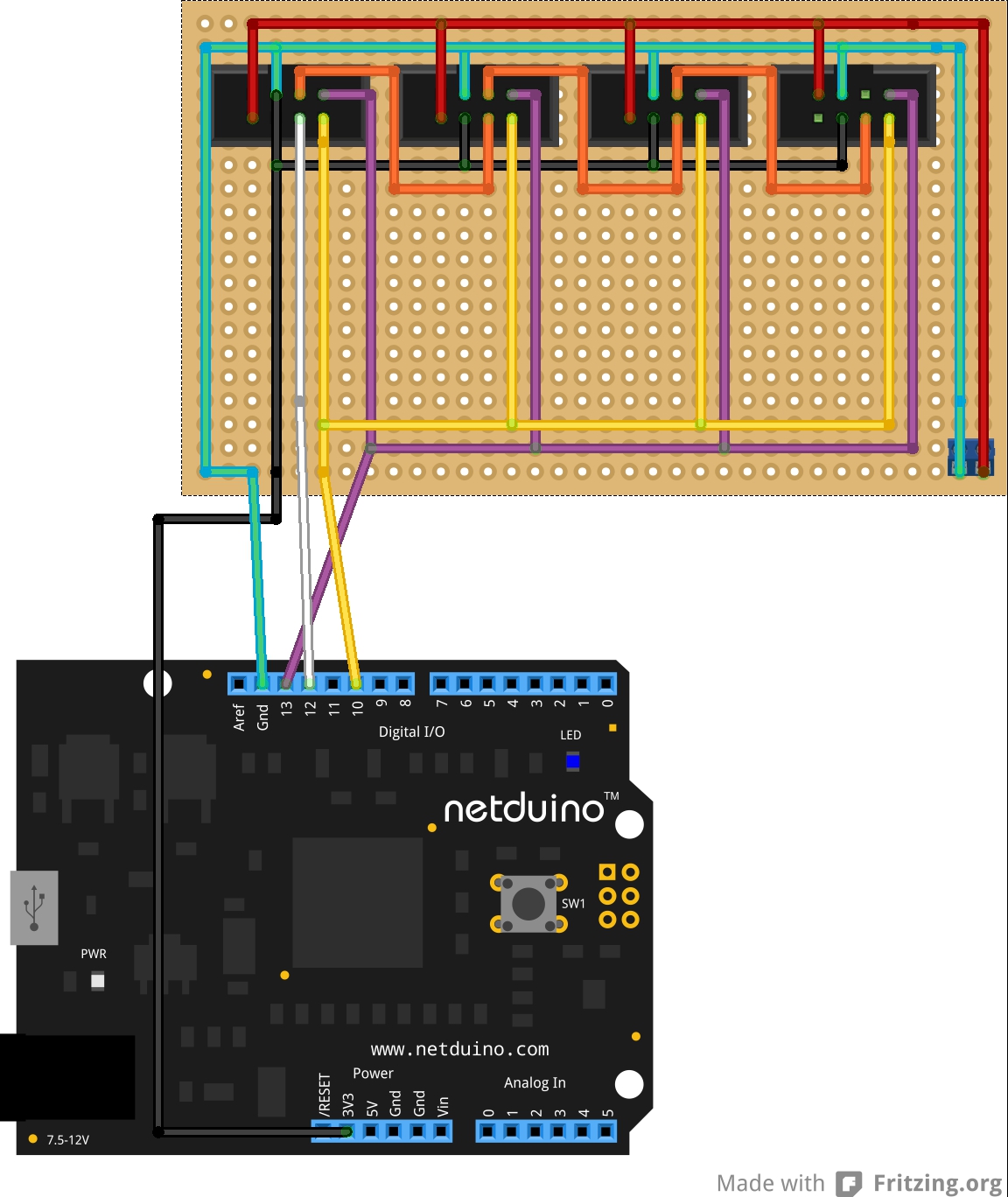
What I am trying to do is create some din rail mounted modules that will provide the switching control for the relays. Each module will use CAT5 connections to connect it back to a central module that will house the netduino and will split the SPI which will be used to multiplex the control logic and distribute the switching voltage from the 24v 3.2A 85W din mounted power supply.
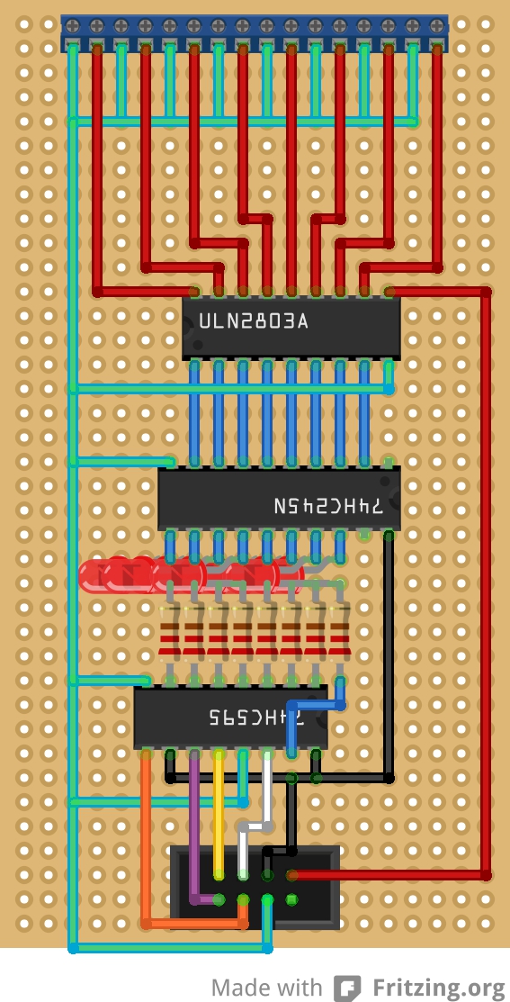
Each module will switch 8x 25amp relays using 24v, will have 8 LEDs to indicate what is on, will contain a 74HC595 shift register, a 74HC245N CMOS and a ULN2803 transitor array, plus some resistors or resitor array.
The relays have approximately a 2.5v 30ma voltage and current drop respectively.
The 4 twisted pairs in the CAT5 will carry the 3 connections for the SPI, 1 connection to return QH from the 595s so they can be daisy chained, common Gnd, 3.3v and 24v.
What I need a little help with is as follows:
Here is a fritzing (see Din Mount Relay_bb.jpg) of what I was thinking for the Din Modules and there is also the netduino shield which distributes the 24v and SPI (see Din Shield_bb), any help moving the LEDs to the 24v side would be much appreciated!
As a key: Red = 24v Black = 3.3v (from netduino) Green = Common Gnd Orange = Returned QH White = MOSI Purple = SCLK Yellow = SS
Andy Attached Thumbnails#52619 A virtual hack night
count me in! | ||||||||||||||
|
||||||||||||||
| This webpage is licensed under a Creative Commons Attribution-ShareAlike License. | ||||||||||||||