hanzibal's Content
There have been 386 items by hanzibal (Search limited from 01-July 24)
#51590 Spark Core (TI CC3000) Porting for Super WiFI Mini?
 Posted by
on 20 July 2013 - 12:39 AM
in
Netduino Mini
Posted by
on 20 July 2013 - 12:39 AM
in
Netduino Mini
Hi guys, I'm back from my holiday now and was looking forward to work on the PCB that I set out to do in Eagle, but...
While I was gone, my commercial IO board launched so I need to attend to that in improving the software, writing docs, creating sample projects and so on. This means I won't have time to work on the PCB for a good while.
I'll be happy to see someone else pick it up instead and since I didn't get farther than removing the mosfets, there's little point in me posting the Eagle files.
#52252 Spark Core (TI CC3000) Porting for Super WiFI Mini?
Posted by
on 21 August 2013 - 07:57 AM
in
Netduino Mini
Wow!
#55448 Spark Core (TI CC3000) Porting for Super WiFI Mini?
Posted by
on 17 January 2014 - 09:48 PM
in
Netduino Mini
Thanks baxter, I'll be sure to make a post when the driver's ready so that I got something to show you.
#51247 Spark Core (TI CC3000) Porting for Super WiFI Mini?
Posted by
on 09 July 2013 - 07:38 AM
in
Netduino Mini
Have you measured the actual power consumption of the the [color=rgb(40,40,40);font-family:helvetica, arial, sans-serif;]CC3000EM while it's fully running?[/color]
[color=rgb(40,40,40);font-family:helvetica, arial, sans-serif;]I blew my [/color][color=rgb(40,40,40);font-family:helvetica, arial, sans-serif;]CC3000EM[/color][color=rgb(40,40,40);font-family:helvetica, arial, sans-serif;] but a new [/color][color=rgb(40,40,40);font-family:helvetica, arial, sans-serif;]CC3000Boost arrived the other day  [/color]
#55479 Spark Core (TI CC3000) Porting for Super WiFI Mini?
Posted by
on 19 January 2014 - 10:15 AM
in
Netduino Mini
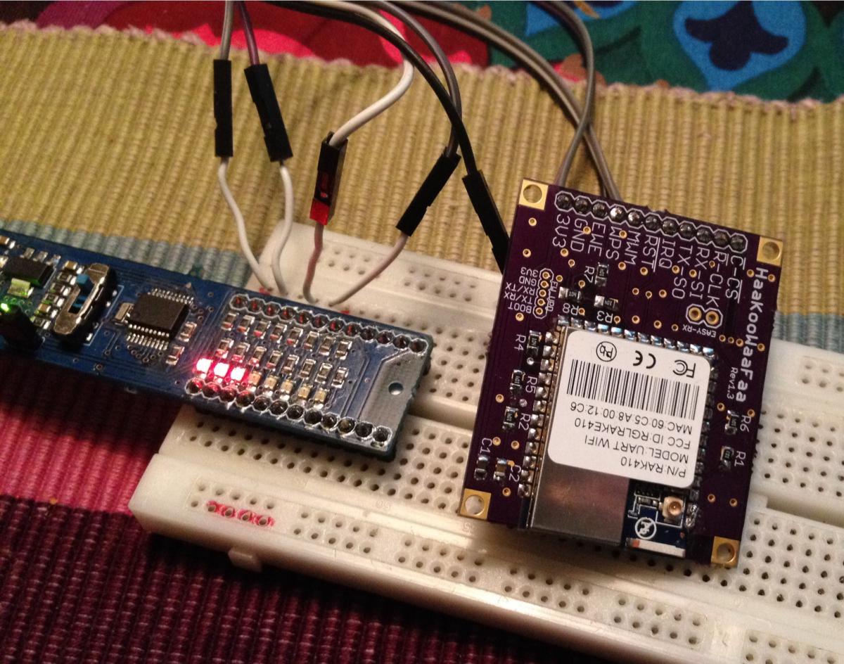
It's based on the RAK410 module, specs are here:
http://www.rakwirele...0_Datasheet.pdf
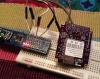 To the left is a PeekyPokey used to explore the API since it's more conveniant to do directly from the PC. When I'm done, I'll move the code to the Netduino.
 To the left is a PeekyPokey used to explore the API since it's more conveniant to do directly from the PC. When I'm done, I'll move the code to the Netduino.
#51138 Spark Core (TI CC3000) Porting for Super WiFI Mini?
Posted by
on 06 July 2013 - 03:00 AM
in
Netduino Mini
Hmm...now I can't sleep trying to figure that one out :-)
#50976 Spark Core (TI CC3000) Porting for Super WiFI Mini?
Posted by
on 01 July 2013 - 07:55 AM
in
Netduino Mini
your radio or host board? I've flicked pwr_en high and low just fine, so maybe double check the wiring, maybe it's OK!
The radio, when trying to set the pwr_en input pin high by applying 3.3V to it, it seems to result in a short circuit.
#51131 Spark Core (TI CC3000) Porting for Super WiFI Mini?
Posted by
on 06 July 2013 - 12:25 AM
in
Netduino Mini
Great, those are some really good guide lines!
Admittedly, I haven't read your posts all that thoroughly yet (it's late over here) and surely there are things to be discussed but just to be clear that I was merely picturing a really basic (yet powerful and versatile) Wifi board for the common Netduino user to benefit from, not the next "Wifi �bershield" :-)
Primarily, I was thinking a Netduino specific board with header layout to match. Heck, the world is overwhelmed by Arduino stuff as it is, and it's not like we would be making a zillion unit thing with a technical height that could withstand more than a week on eBay given every little peace of additional hardware adds to overall costs in terms of time and consequently that of gold.
Basically making a few simple mods to that github board (undoubtedly nice work) in order to get a cheap, quick and dirty wifi board for the whole Netduino family of boards (not excluding the mini) with a managed driver to go as I know of which the ancient lady warrior being extremely resourceful when it comes to the latter of things :-)
@ziggurat29: Have you ever considered politics or have they perhaps already got to you?  SMD.
SMD.
#50619 Best Hobby Oscilloscope
Posted by
on 18 June 2013 - 06:40 PM
in
General Discussion
Hi!
The logic sniffer seems ok for UART and PWM analyzis but not as an oscilloscope:
The analogue bandwidth of 200kHz is way too low and makes it pretty useless
The display is tiny, mine is many times bigger and I still wish it was a lot bigger
Buffers are very small, you can only see small fragments at a time
I think these kind of gadgets are rather cool but don't qualifiy as oscilloscopes. It's like they thought "We got this tiny piece of hardware, let's see if we can make an oscilloscope out of it". It would be better if they'd thought "hey, let's design an oscilloscope and choose whatever hardware meets the requirements".
No, I would put my money on something else.
#56689 Automated Urban Garden
Posted by
on 07 March 2014 - 06:55 AM
in
Project Showcase
To think there are more than one manufacturer of such things, incredible really!
#56671 Automated Urban Garden
Posted by
on 06 March 2014 - 11:49 AM
in
Project Showcase
Great project!
If you need more sensors, you could try interfacing the Parrot Flower Power:
http://www.parrot.com/flowerpower/en/
It would require a Bluetooth LE module and probably hacking their protocol. The flower power is a bit expensive but there's also the SensorTag from Texas which is not miles away (not a coinsidence):
http://www.ti.com/tool/cc2541dk-sensor
#56685 Automated Urban Garden
Posted by
on 06 March 2014 - 09:31 PM
in
Project Showcase
The SensorTag is just 25 dollars :-)
I got one, works perfecly with iOS devices but haven't got around getting a board for my Netduinos yet and turned out there's no BT LE drivers for my good old XP box (while as it is built into Win 7).
I got one, works perfecly with iOS devices but haven't got around getting a board for my Netduinos yet and turned out there's no BT LE drivers for my good old XP box (while as it is built into Win 7).
#56202 Networked music player using the mini
Posted by
on 19 February 2014 - 12:15 PM
in
Project Showcase
Great, that you found it useful!
I saw your antique radio project and I really love the mix of new and old that you get from putting new internals in old machines.
My late mother used to have one similar to yours, you'd have to wait for like 15 minutes for it to get warm before you could use it. Sadly, we didn't keep it.
Cheers!
#57935 Networked music player using the mini
Posted by
on 04 May 2014 - 06:17 PM
in
Project Showcase
SCI_VOL is a h/w register of the vs1053b chip, so you need to write the value 0x2424 to the register. You do this using the serial command interface (hence the "SCI" prefix) over SPI.
    // Write to an  SCI register
    private void WriteRegister(byte address, ushort data, bool waitForDREQ = true)
    {
        wr_buff[0] = 2;                    // write command
        wr_buff[1] = address;              // register
        wr_buff[2] = (byte)(data >> 8);    // high byte
        wr_buff[3] = (byte)(data & 0xff);  // low byte

        SelectCommand();                   // select SCI
        if (waitForDREQ) AwaitDREQ();      // wait for dreq to go high
        spip.Write(wr_buff);
    }

    // example of setting volume
    WriteRegister(REG_SCI_VOL, 0x2424);
The code snippet above is taken from my source code (puplished earlier).
I would use a rotary encoder but if you want to use a potentiometer, you can set it up as a simple voltage divider GND - 3.3V and then read the voltage of the wiper using a Netduino analogue pin. You would then need to add software to continuously poll the analogue pin for any changes in voltage, executing the corresponding volume adjustments.
#58076 Networked music player using the mini
Posted by
on 12 May 2014 - 06:36 PM
in
Project Showcase
The 16 bit register is divided into two bytes of 8 bits (256 steps) each, you need to set the two bytes separtely like so:
byte left_vol = 45;
byte right_vol = 90;

ushort vol = (left_vol << 8) + right_vol;

WriteRegister(REG_SCI_VOL, vol);
#56344 Extensive driver for the MCP23S17 I/O expander
Posted by
on 24 February 2014 - 07:31 PM
in
Project Showcase
Problem ought to be the Object.GetHashCode method returning the same value for two different instances which I never anticipated in the context of how it's being used here.
Among other things, MSDN says this about GetHashCode:
I'll figure something out - meanwhile you could try using only Bank 0 and see if you can get that working....The GetHashCode method can be overridden by a derived type. If GetHashCode is not overridden, hash codes for reference types are computed by calling the Object.GetHashCode method of the base class, which computes a hash code based on an object's reference; for more information, see RuntimeHelpers.GetHashCode. In other words, two objects for which the ReferenceEquals method returns true have identical hash codes...
#56343 Extensive driver for the MCP23S17 I/O expander
Posted by
on 24 February 2014 - 07:16 PM
in
Project Showcase
Hmm, thats odd - it's the multi SPI mgr reporting an attempt to add the same object twice.
Let me get back to you shortly...
#56262 Extensive driver for the MCP23S17 I/O expander
Posted by
on 22 February 2014 - 01:30 AM
in
Project Showcase
Looking great! A couple of things though:
1. You should connect D12 to MISO (assuming you got a Netduino 2).
2. There's a bug in your code - when looping to create your 16 output ports, you cannot pass in counter values 0,1,2,3,4,5,6,...etc casted as pins since these need be integer powers of two, e.g. 1,2,4,8,16,32,64,...etc. You can achieve this like so:
for (uint Counter = 0; Counter < pinCount; ++Counter) Outs[Counter] = chip1.CreateOutputPort((MCP23S17.Pins)(1 << Counter), false);However, I really think you should be using the enums, then your code will be easier to read and will work even if I change the implementation. For example, you would have avoided the above bug :-) I see your expander board has the IRQ pins broken out after all which is great news but you might want to add that later when you got the basics working. Hope this helps!
#56236 Extensive driver for the MCP23S17 I/O expander
Posted by
on 20 February 2014 - 09:23 PM
in
Project Showcase
Oh and even though its probably obvious, I should maybe point out that the driver presents the two banks (A0...A7 and B0...B7) as one consecutive pin array 0...15.
Microchip tend to use "bank switching" due to legacy tech in how registers of their MCUs are mapped to memory. Most of their chips are probably PIC 18's running custom read-only firmware :-)
#56200 Extensive driver for the MCP23S17 I/O expander
Posted by
on 19 February 2014 - 10:54 AM
in
Project Showcase
What's this?
This thread is about a software driver for a chip called MCP23S17 that provides 16 additional digital IO pins to a micro controller such as the one on your Netduino.
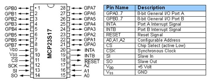
The MCP23S17 gives you 16 digital input, output and interrupt enabled pins over SPI. Up to eight chips can be combined on a single SPI bus to provide a maximum of 128 pins.
Background
I was originally looking to make a dual ] board (Arduino shield form factor) for this driver to be used with. As so often however, I haven't found the time to complete the board so I decided to release the driver code for others to use.
About the software
The driver class is actually quite powerful and has a lot of features. The whole interface somewhat mimics that of native Netduino GPIOs in how they are created and used. Full source code is attached to this post.
You can create individual pins (input, output, interrupt) and also buses to represent a collection of pins in parallell.
The buses are very powerful - for example, you can easily create a 4 pin bus to be used in controlling an LCD or something like that.
You can also read and write pins or buses in a so called "burst mode" - this will result in bit streams in either direction at about a tenth of the configured SPI speed.
The driver can also be used in a special "direct mode" where all the built-in code for thread safe pin management etc is bypassed in favor of more speed.
How to use it
Simply download the attached code file and add it to your project and start coding with it - these lines of code the only ones needed for an output port:
I'd love for you guys to try it out and then hear about your experiences!
Hardware
Obviously, you need one or more MCP23S17 chips as well. The chip is available in a breadboard friendly DIP28 package and breakout boards are available on eBay and other places.
You wire the chip just as you would any other SPI slave device - connect power, ground, miso, mosi, clock, chip select and optionally an additional pin to receive interrupts.
NOTE: This driver is for the SPI version of the chip, i.e. MCP23S17 and not the regular MCP23017 which uses I2C. I was planning on isolating the transport layer to support both but I will probably never get around doing that so if you're up for it...feel free!
Code revision history:
v1.1 - corrected a bug involved in cascading
v1.2 - added internal multi SPI mgr
V1.3 - made a few insignificant clean ups
v1.4 - corrected a nasty bug in the multi SPI mgr
 MCP23S17.cs 57.85KB
62 downloads
MCP23S17.cs 57.85KB
62 downloads
This thread is about a software driver for a chip called MCP23S17 that provides 16 additional digital IO pins to a micro controller such as the one on your Netduino.
The MCP23S17 gives you 16 digital input, output and interrupt enabled pins over SPI. Up to eight chips can be combined on a single SPI bus to provide a maximum of 128 pins.
Background
I was originally looking to make a dual ] board (Arduino shield form factor) for this driver to be used with. As so often however, I haven't found the time to complete the board so I decided to release the driver code for others to use.
About the software
The driver class is actually quite powerful and has a lot of features. The whole interface somewhat mimics that of native Netduino GPIOs in how they are created and used. Full source code is attached to this post.
You can create individual pins (input, output, interrupt) and also buses to represent a collection of pins in parallell.
The buses are very powerful - for example, you can easily create a 4 pin bus to be used in controlling an LCD or something like that.
You can also read and write pins or buses in a so called "burst mode" - this will result in bit streams in either direction at about a tenth of the configured SPI speed.
The driver can also be used in a special "direct mode" where all the built-in code for thread safe pin management etc is bypassed in favor of more speed.
How to use it
Simply download the attached code file and add it to your project and start coding with it - these lines of code the only ones needed for an output port:
// create driver to use SPI bus #1 and Netduino pin 17 for chip selectvar chip = new MCP23S17(var io = new MCP23S17(SPI.SPI_module.SPI1, Pins.GPIO_PIN_17);// create a port for pin 1var outport = chip.CreateOutputPort(MCP23S17.Pins.GPIO_1);// drive pin 1 highoutport.Value = true;There are more examples abailable in posts ahead. There's currently no separate documentation for the software but it's easy to adopt and there are lots of intelli-comments in the code to help guide you through.
I'd love for you guys to try it out and then hear about your experiences!
Hardware
Obviously, you need one or more MCP23S17 chips as well. The chip is available in a breadboard friendly DIP28 package and breakout boards are available on eBay and other places.
You wire the chip just as you would any other SPI slave device - connect power, ground, miso, mosi, clock, chip select and optionally an additional pin to receive interrupts.
NOTE: This driver is for the SPI version of the chip, i.e. MCP23S17 and not the regular MCP23017 which uses I2C. I was planning on isolating the transport layer to support both but I will probably never get around doing that so if you're up for it...feel free!
Code revision history:
v1.1 - corrected a bug involved in cascading
v1.2 - added internal multi SPI mgr
V1.3 - made a few insignificant clean ups
v1.4 - corrected a nasty bug in the multi SPI mgr
MCP23S17.cs 57.85KB
62 downloads
Attached Thumbnails
#56312 Extensive driver for the MCP23S17 I/O expander
Posted by
on 23 February 2014 - 09:05 PM
in
Project Showcase
Yes it is because you are passing in the same SPI module to multiple driver instances.
As I said earlier, the driver does not yet support the same SPI module being shared among multiple driver instances.
I have to make a few adjustments for that first.
Also, I think your pin numbering might still be wrong - you must use values that are integer power of two, e.g. 1,2,4,8,16, etc. Have a look at the example I provided in post #15 above where I'm bit shifting like this "1 << Counter".
While waiting for me to update the code, you'd probably benefit more from verifying the driver works in getting a single single chip up and running.
#56313 Extensive driver for the MCP23S17 I/O expander
Posted by
on 23 February 2014 - 09:08 PM
in
Project Showcase
Yes, that's an excellent idea - and it would be really cool to see the software being used to drive an LCD too! TIP: Try using BurstWrite on a bus... Thanks to the pins A0,A1,A2 of each chip (reflected through the hwAddr constuctor parameter), you can cascade up to 8 chips on the same SPI bus producing a maximum of 128 GPIOs all with the same CS line - but, I need to make a few adjustments to allow the same SPI module to be shared among multiple driver instances. At present, such an attempt would result in an exception of type "resource already in use" or something like that - just like mcinnes01 just experienced. NOTE: The driver is for the SPI version, e.g. the MCP23S17 with an "S" in the middle - not the regular MCP23017 which runs on I2C.ok.. another great work Andy. so... actually i dont need to drive LCD display using M74HC595. I think it should be easier to drive it using MCP2317....
thanks in advance for hanz and andy.
#56319 Extensive driver for the MCP23S17 I/O expander
Posted by
on 23 February 2014 - 10:24 PM
in
Project Showcase
I just updated the driver code in post #1 - it now contains an internal light weight multiple SPI manager so you shouldn't be getting that exception anymore. Please try it when you can and report back since I haven't actually tested it myself yet....Any ideas?...
 because all my Netduinos are occupied
This also means sharing a single SPI bus among multiple driver instances should work, both when cascading using a shared CS line and when using separate per chip CS lines.
EDIT: Sorry for messing with your code, but may I suggest:
because all my Netduinos are occupied
This also means sharing a single SPI bus among multiple driver instances should work, both when cascading using a shared CS line and when using separate per chip CS lines.
EDIT: Sorry for messing with your code, but may I suggest:
for (int ic = 0; ic < icCnt; ic++){ chip[ic] = new MCP23S17(SPI_Devices.SPI1, Pins.GPIO_PIN_D10, Pins.GPIO_NONE, ic, 7000); // Define all outputs for (int pin = 0; pin < pinCnt; pin++) Outs[16 * ic + pin] = chip[ic].CreateOutputPort((MCP23S17.Pins)(1 << pin), false);}Really anxious to know if the driver works with your board!
#56315 Extensive driver for the MCP23S17 I/O expander
Posted by
on 23 February 2014 - 10:04 PM
in
Project Showcase
Cool, so you "only" need to write your own LcdProvider class where you would then make internal use of the MCP23S17 driver in creating and using a bus from the pins you supply in the parameter list above - correct?
#56341 Extensive driver for the MCP23S17 I/O expander
Posted by
on 24 February 2014 - 07:02 PM
in
Project Showcase
Ah, I see it now, in the inner for loop, you should replace pinCnt with icPins.
Sorry, I think that was my fault, I misinterpreted your variable naming.
Hopefully, it will work after that mod.


