Netduino home hardware projects downloads community

Jump to content


The Netduino forums have been replaced by new forums at community.wildernesslabs.co. This site has been preserved for archival purposes only and the ability to make new accounts or posts has been turned off.

CW2's Content

There have been 148 items by CW2 (Search limited from 03-July 24)


By content type

See this member's


Sort by                Order  

#60658 Controlling 2WD Chassis using Motor Driver 1A Dual TB6612FNG

Posted by CW2 on 07 November 2014 - 02:57 PM in Netduino Plus 2 (and Netduino Plus 1)

I have checked the datasheet again and I think there is a problem with control signal voltage levels: if you power the motor control board by 5 - 6 V, the Netduino 3.3V outputs do not have high enough voltage (VIH = 0.7*VCC = 0.7*5 = 3.5V).


So, connect VCC to Netduino 3.3V, STBY to 3.3V, VM to 5-6V.


To manually test the motors, connect PWM to 3.3V and then either IN1 or IN2 to 3.3V. 


#60653 Controlling 2WD Chassis using Motor Driver 1A Dual TB6612FNG

Posted by CW2 on 07 November 2014 - 11:57 AM in Netduino Plus 2 (and Netduino Plus 1)

Can you share the photo of the actual wiring?


#57316 .NET MF 4.3 QFE1 RTM

Posted by CW2 on 03 April 2014 - 06:46 AM in General Discussion

The SDK and Porting Kit Documentation link was fixed today  ;)


#60125 Building custom Netduino Mini

Posted by CW2 on 16 September 2014 - 08:55 AM in Netduino Mini

To get some ideas, have a look at the schematics (pdf, from the downloads page), there is also board file (for Cadence Allegro Viewer, does not work in Eagle). The microcontroller is AT91SAM7X512-CU.
 
However, AT91SAM7 is rather old and there is no 4.3 firmware - you might want to consider a more recent microcontroller, such as Cortex-M3/M4, which are very popular.
 
Community member Juzzer has done some amazing work regarding custom designed boards, also see his posts in GHI forums.


#59984 Safe code to convert byte[4] to float

Posted by CW2 on 04 September 2014 - 06:19 AM in General Discussion

The BitConverter class was added in .NET Micro Framework 4.3.


#57784 Has anyone successfully used a HS1101 humidity sensor?

Posted by CW2 on 27 April 2014 - 08:24 AM in Netduino 2 (and Netduino 1)

You should be able to use TristatePort for that:

// Initially set to input mode
var port = new TristatePort(Pins.GPIO_Pin_D0, false, false, ResistorModes.Disabled);

port.Active = true; // set to output mode
port.Write(true);
...
port.Active = false; // set to input
port.Read();

Note: In your original code, you'd have to dispose the port object before another one can be created - add RCtime.Dispose() before ... = new InputPort(...).


#58437 Creating a custom board with Netduino firmware?

Posted by CW2 on 27 May 2014 - 05:54 PM in Netduino 2 (and Netduino 1)

For example, pin "PA2" is called "PA2/UART2_TX". Is that the pin-configuration that just the Netduino firmware uses, so that when I create the Fritzing part I should name the pins with the shortname?


That pin configuration is microcontroller-specific. It means the GPIO pin is shared (multiplexed) with another peripheral - it can be configured as third pin of GPIO port A, or TX line of UART2. There is a big table in the datasheet  :P that describes pin functions - most pins have more than one features (I think theoretically up to 15 in ST micros) and sometimes the same signal can be enabled on different pins (e.g. UART2 TX is available also on PD5).


Regarding the names in schematic symbols, it depends - you'd probably need to include at least the GPIO identifier and maybe the alternate function when it is important in your design - like in the above example, "PA2/UART2_TX" indicates the use of TX serial line. Listing all the available features on each pin would require quite large symbol, but I have seen such schematics too (usually, the part is split into several symbols that contain logically grouped features). I think in Fritzing, you can have additional information in the pin description, which is displayed in form of tooltip...


#58428 Creating a custom board with Netduino firmware?

Posted by CW2 on 27 May 2014 - 02:08 PM in Netduino 2 (and Netduino 1)

Have a look at the description in the datasheet, it explains it in great detail.

  • When BOOT0 is logic 0, the code executes from flash - this is what you want for 'normal' operation,  i.e. .NET MF running; the pull-down resistor R12D ensures the logic 0 level,
  • When BOOT0 is logic 1 (switch pressed) then BOOT1 determines if the code executes from system memory (logic 0, ROM Bootloader), or embedded SRAM (logic 1). You usually want the ROM bootloader to be executed, hence the second pull-down resistor R11D. BOOT0 is a dedicated pin, while BOOT1 is shared with GPIO (PB2) - it is sampled a few cycles after reset, then it can be used as regular GPIO.

The use of the rest of bootloader pull-up/down resistors is described in the Application Note 2606: basically, when a peripheral (USART, CAN, USB) is used to connect to the bootloader, its "pins have to be kept at a high or low level and must not be left floating during the detection phase".


#59622 Creating a custom board with Netduino firmware?

Posted by CW2 on 08 August 2014 - 08:44 PM in Netduino 2 (and Netduino 1)

Impressive. Hats off to doing it all in Fritzing.


#57035 Interrupt Port and Input Port Read Values are Wrong on First Interrupt.

Posted by CW2 on 23 March 2014 - 08:44 PM in General Discussion

I have not tried to reproduce the behavior, but there is one fundamental issue with using port.Read() in the interrupt handler: because the interrupts are queued, the handler is executed after a certain period of time, thus port.Read() returns the port state at the time the interrupt handler is being executed, not when the interrupt occurred. This can cause incorrect results, especially when the pulse duration or frequency is close to execution time of the interrupt handler (managed code).


I guess a better way is to use two interrupt ports, both set up for falling and rising edge (InterruptEdgeBoth) and use the handler parameters data1 (port number), data2 (port state, 1/0) and timestamp in a state machine (you can reuse one xxx_OnInterrupt handler).


#59386 Control 80V DC Motor/Bulb Using Netduino 2

Posted by CW2 on 25 July 2014 - 11:50 AM in General Discussion

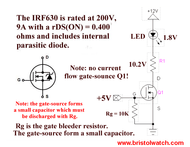
You cannot switch voltage polarities, you'd need to use different kind of transistor (N-channel vs. P-channel MOSFET).


Technically, you can change values, as long as the difference is the same. Voltage is electrical potential difference between two points, so 0 .. 60V is the same as -60 .. 0V which is the same as 37.2 .. 97.2V (because 60 - 0 = 0 - (-60) = 97.2 - 37.2 = 60V); but switching wires 60 .. 0V is different (0 - 60 = -60V, negative). You can destroy electrical parts with wrong voltage.


If you don't connect Netduino ground and your power supply ground, the circuit most likely will not work (unless there is a common ground connection, for example when you power the Netduino from the same power supply as the motor/bulb).


By moving the resistor, you've completely changed the circuit behavior - previously, the resistor (between gate and ground, "pull-down") ensures safe 'off' state, it means the switch is guaranteed to be off until you set Netduino pin to high. Now, the resistor in series (between Netduino pin and gate) just limits the current - it does not do any harm, but it is also useless, because MOSFET is driven by voltage, not by current (you'd need this resistor for BJT transistor, to limit base current). Additionally, you've lost that 'safe-off' feature, and you could get unexpected behavior, because Netduino pin is in 'floating' (high-impedance) state during startup, until you create the OutputPort instance, thus switching it to digital output mode.


If you really want to understand how the electronic works, have a look at sites like All About Circuits or Electronics Tutorials, they can explain it much better than me :)


#59389 Control 80V DC Motor/Bulb Using Netduino 2

Posted by CW2 on 25 July 2014 - 12:52 PM in General Discussion

Yes, if you want to control the positive wire, you'd need P-channel MOSFET. The control logic is inverted, low gate voltage is 'on', high gate voltage is 'off'; and there should be a "pull-up" resistor between gate and +V to ensure safe 'off' state.


Yes, N-channel MOSFET is cheaper than P-channel; N-channel is a little bit better (lower resistance, which means lower power losses, which means smaller heatsink : )


#59394 Control 80V DC Motor/Bulb Using Netduino 2

Posted by CW2 on 25 July 2014 - 01:54 PM in General Discussion

There is one major problem with interfacing P-channel MOSFET to a microcontroller when switching [relatively high] voltage - when the control circuit closes, the switched voltage (i.e. 12, 60 or 80V) is applied to the microcontroller pin and it will be destroyed, because Netduino max pin voltage is less than 10V.


You have to use second N-channel MOSFET (or NPN BJT) placed between Netduino pin and P-channel MOSFET gate to control it. The proper circuit looks like this:


MOSFET_high_side_driver.png


You can replace Q3 + R3 with N-channel MOSFET (use R3 as pull-down, connected between gate and ground to ensure safe 'off' state).


I would recommend you to get a few different transistors and try low voltage (3.3V - 5V) circuits first, switching simple loads like LED and evaluate the possible configurations. After you understand how they work, you can 'upgrade' to higher voltage and current. Random messing with wires without understanding the basics is not going to end well...


#59382 Control 80V DC Motor/Bulb Using Netduino 2

Posted by CW2 on 25 July 2014 - 08:22 AM in General Discussion

The voltage naming notation is a little bit confusing in the article - just use "GND" (0V) for the black wire and and "+V" (12V .. 80V) for the red one. The transistor in the circuit act as a switch that terminates or connects the load to GND (ignore the voltage numbers in the picture):


tr8.gif


#59372 Control 80V DC Motor/Bulb Using Netduino 2

Posted by CW2 on 24 July 2014 - 07:31 PM in General Discussion

CW2 : Thank you too, but Im very sorry. I'm very new to these things, so half of things you said, just bounced off my head. But yes I'm learning through web sites, as always not easy. :)


There is really no need to apologize. How about this article? (replace Arduino with Netduino, and of course the application code has to be different, but the principle remains the same).


#59380 Control 80V DC Motor/Bulb Using Netduino 2

Posted by CW2 on 25 July 2014 - 07:29 AM in General Discussion

Well, you could use PWM, but for simple on/off control it is easier to start with a digital pin:
 

public static class Program
{
  public static void Main()
  {
    // Motor/Bulb connected to D3
    var motor = new OutputPort(Pins.GPIO_PIN_D3, false); // Initially off

    while(true)
    {
      motor.Write(true);   // On
      Thread.Sleep(500);
      motor.Write(false);  // Off
      Thread.Sleep(500);
    }
  }
}

Technical notes about the RFP30N06LE transistor (datasheet pdf) used in the bildr.org article:

  • It has maximum voltage 60V - enough for 12V bulb, but not enough for 80V motor.
  • It can be controlled directly from Netduino pin, it requires at least 2V gate voltage (Netduino has 3.3V output).
  • It is rated for 30A continuous current, it can switch about 20A at 3.3V gate voltage. You'd need higher gate voltage for higher load current, i.e. another small transistor to control this power MOSFET.


#59367 Control 80V DC Motor/Bulb Using Netduino 2

Posted by CW2 on 24 July 2014 - 12:03 PM in General Discussion

Could you please help, assuming motor is a bulb and DC output is 12V (external, not from netduino).


In this simple scenario, i.e. controlling 12V DC bulb from Netduino, you can use just a transistor switch.


You'd need to calculate the load current IL = P/V, where P is the bulb power rating and V is the voltage, so for example for a small 4W automotive light bulb the current is 4/12 = 0.33 A. Then you select a transistor that can handle such current, preferably a MOSFET. In this particular case of relatively small current, you should be able to find a suitable MOSFET that has 'logic level' control, i.e. gate voltage threshold <3V, so you can control it directly from [3.3V] Netduino pin. Otherwise, you'd need another 'general purpose'/'small signal' transistor (BJT or MOSFET) to control the 'big' power transistor (which typically requires ~10V gate voltage for the rated current).


Regarding the DC motor control: if you only need simple control, i.e. on/off switch, then the 'bulb switch' circuit can be used in the same way, assuming the transistor has appropriate current rating; and it is recommended to add a flyback diode (to handle current spikes generated when motor changes its state). Otherwise, I would consider using a specialized motor driver ("H-Bridge"), as suggested by Mario. (You can use H-Bridge for the bulb too.)


There is a lot of information available on the Internet about how to control a transistor switch from a microcontroller output, including complete circuit schematic, part selection etc.


#56773 Emulator, can it handle OneWire ?

Posted by CW2 on 12 March 2014 - 06:29 PM in General Discussion

hi, is there a software to search the address of ds18b20?


What exactly would you need to do? The 1-Wire protocol has built-in mechanism for enumerating the devices present on the bus, all implementations I've seen support that - in the particular case of .NET Micro Framework, have a look at OneWire.FindAllDevices() method.


#57894 Azure Service Bus Connection

Posted by CW2 on 02 May 2014 - 03:18 PM in Visual Basic Support

I'd like to see a good (i.e., not OpenSSL) and light-weight (i.e., not OpenSSL) open source TLS implementation for NETMF boards like the Netduino as well. 


Have you had any chance to evaluate PolarSSL or CyaSSL?


#56508 Compiling Custom Netduino Firmware: Step-By-Step Instructions - Help

Posted by CW2 on 27 February 2014 - 10:51 PM in General Discussion

Assumptions: Using Netduino 4.3 firmware/framework, and 4.3 SDK and VS2012 Express.


The Express edition is not enough for building the firmware, you need Visual C++ compiler too, that means Visual Studio 2012 Professional or higher.


#56867 Compiling Custom Netduino Firmware: Step-By-Step Instructions - Help

Posted by CW2 on 17 March 2014 - 12:48 PM in General Discussion

Any update on this?


Please have a look at Netduino 2 Firmware v4.3.1 with GCC support


#56570 Compiling Custom Netduino Firmware: Step-By-Step Instructions - Help

Posted by CW2 on 02 March 2014 - 07:19 AM in General Discussion


setenv_base.cmd GCC4.6 PORT c:\yagarto-4.6.0


The 'PORT' parameter is not used in NETMF 4.3, you should call setenv_gcc.cmd:


setenv_gcc.cmd 4.6.2 C:\Yagarto-4.6.2


The version number (4.6.2) must match the directory name in lib\gcc\arm-none-eabi.


#56577 Compiling Custom Netduino Firmware: Step-By-Step Instructions - Help

Posted by CW2 on 02 March 2014 - 12:40 PM in General Discussion

EDIT: the first error seems to happen when building TinyBooter, it says the target CPU doesn't support ARM mode

 
The Cortex-M is not supported in the build files, you'd have to add appropriate -mcpu directive in the Microsoft.Spot.System.GCC.Targets file; plus a few other changes. The easiest way is to download Microsoft.Spot.system.gcc.targets from NicolasG's repository, copy it into \Tools\Targets directory (overwrite the existing one).
 
However, you'll get several other errors, some were introduced in BitConverter.cpp, also there are missing GCC scatterfiles in Netduino2 solutions, which are mandatory for the linker.
 
I am now working on fixing GCC support for Netduino2 solutions, I'll publish the source code with detailed instructions when it's done.


#59907 Convert Arduino Library To Netduino

Posted by CW2 on 26 August 2014 - 04:18 PM in General Discussion

Now I am getting a bunch of "the name ______ does not exist in the current context."


Well, those are Arduino library function calls and some constants - the good news is you don't need to convert that, just implement spiTransfer() function to call .NET Micro Framework SPI.Write() method and delete all pinMode(), digitalWrite() etc. calls, which are not needed (because SPI class does that internally; including the ChipSelect pin if you set it in the configuration).


#59914 Convert Arduino Library To Netduino

Posted by CW2 on 27 August 2014 - 07:08 AM in General Discussion

Well, how should I put this... the whole LedControl code is basically one SPI.Write() method call to transfer 16 bit data (spiTransfer() function) to the MAX and a few methods that set the data to perform the desired command.
 
Personally, I would stop converting the Arduino code and start with C# from scratch, using the device datasheet as reference and the Arduino code if in doubt (assumed to be working). There is also possibility that the converted code will not work at the first try, so you'd need to troubleshoot it, and it is much easier to troubleshoot code you understand well (e.g. written yourself).
 
Create a new project and start talking to the MAX using the SPI class, it should be something like this: 

...
public static void Main()
{
  var max = new SPI(new SPI.Configuration(...));
  var data = new byte[2]; // 16 bits (address + 8 bit data)

  // Display test mode
  data[0] = 0x0F; // Address
  data[1] = 0x01; // Test mode on

  max.Write(data);

  Thread.Sleep(Timeout.Infinite);
}

Once you get the code working (written from head, so probably does not even compile, data buffer can be ordered the other way round etc.), you can add command constants and wrapper methods, then you will be able to use the Arduino code because you'll see what it does and where it fits.


home    hardware    projects    downloads    community    where to buy    contact Copyright © 2016 Wilderness Labs Inc.  |  Legal   |   CC BY-SA
This webpage is licensed under a Creative Commons Attribution-ShareAlike License.