Posted by
Andy,
You can use a single pole double pole switch. The center contact goes to the coil (other side to ground).
uC-----o o----- pwr supply
spdt switch
o
coil
Chuck
|
||||||||||||||
carb's ContentThere have been 185 items by carb (Search limited from 06-July 24) #52382 Help bypass switch with reverse current protection
Andy,
You can use a single pole double pole switch. The center contact goes to the coil (other side to ground).
uC-----o o----- pwr supply
spdt switch o coil
Chuck #36601 Simple wiring question
No Problem, The relay has contacts the same as a switch. I actual ran the code on a Netduino Classic 4.2 firmware. There are a lot of code that you can pull snippets from on the forum, I have been mainly using visual basic, but pulled the code snippet from the project pages "pushing the button, action and reaction" project to make sure I had the correct syntax for C#. Chuck #36582 Simple wiring question
Perkunas, Unless I am missing something you do not need a pullup to make the circuit work. The following code works fine with a Netduino Classic:
using System;
using System.Threading;
using Microsoft.SPOT;
using Microsoft.SPOT.Hardware;
using SecretLabs.NETMF.Hardware;
using SecretLabs.NETMF.Hardware.Netduino;

namespace NetduinoApplication1
{
  public class Program
  {
    public static void Main()
    {
      InputPort D0input= new InputPort(Pins.GPIO_PIN_D0,false ,Port.ResistorMode.PullUp);
      OutputPort Led = new OutputPort(Pins.ONBOARD_LED, false);
      bool inputstate = false;
      while (true)
      {
        inputstate = D0input.Read();
        Led.Write(inputstate);
        Thread.Sleep(100);
      }
    }
  }
}
The advantages are:
You can test by placing a jumper wire from ground to D0, which takes it to zero voltage i.e. false. This turns the onboard LED off, remove the wire the internal pullup brings D0 to 3.3vdc i.e. true, onboard LED comes on. If you want to output to a DIO, change from Onboard_LED to one of the Digital Outputs. Hope this help, Chuck #36654 Dead Mini
Jack, Managed to update my Netduino Mini today using a Synapse Netduino Mini Breakout board that I got from Jameco. I had a few problems, but finally got it to work. The board connects via USB, but must be selected to RS232. It showed up as Com3, ended up using Sam-Ba 2.11 due to communication error that I got with 2.12 (may have had the board selected to TTL at the time, not sure). I could have tried a higher voltage supply to the breakout but it did update at 5 vdc from the USB. Tested the board okay after I figured out that Pin 17 was PWM0. Good luck, Chuck #42563 What was and what's to come � A look back through 2012 and some thoughts...
Steve,
Good recap of the year. If you could throw in a few free items you may be able to get a job in politics. But with your honesty I am not sure you could get into our Democrat or Republican parties.
Happy New Year, I look forward to more great things to come.
Chuck #43244 Multiple i2c -bmp085 and lcd shield
Jim,
I don't know if I can help but I need a little more information.
Which board are you using, Netduino Plus or the Plus 2?
You have both devices on I2C, which addresses are you using? The I2C can normally be 1 - 8 (in binary). The 2 devices need to be on different address.
Do the LCD and the BMP085 work separately?
Which firmware are you using?
Also if you can provide some source code that would help to locate a problem.
Are you using Stefan's Toolbox?
Will help if I can, but without additional information it is like asking the question "how many marbles are in this jar, true or false?"
Chuck #36627 My Simple Go Module wishlist
Arron, maybe could reduce the current some but I was looking to be able control a motor contactor or a SSR for water heater etc. A motor driver would likely work, I was thinking of using a mosfet for the output. Chuck #36606 My Simple Go Module wishlist
Chris, Both terminal and headers would be nice, I have been thinking about an output board for driving LEDs or relays (mechanical and Solid State) that could sink 100 to 200 ma per output. Just haven't gotten enough time to start it. Chuck #36626 My Simple Go Module wishlist
Jack,
One of the forum members has a shield that gives you 32 DIOs Multiplexor Shield. It should work on the shield base. i have one but haven't used it yet. Chuck #39597 USB for custom made board
Nissim, The files are located in the Pinned thread at the top of this forum and on the download page. #38141 Anyone else building Netduino Powered Halloween Props?
Giuliano,
I purchased a couple of the Parallax Rev B PIRs. I connected one the PIRs to my Netduino Classic, and it worked fine without a pull resistor. I wrote sample code to operate the onboard LED and a digital output for a relay. Connecting the PIR to Ground, 3.3 vdc and D2 using System;
using System.Threading;
using Microsoft.SPOT;
using Microsoft.SPOT.Hardware;
using SecretLabs.NETMF.Hardware;
using SecretLabs.NETMF.Hardware.Netduino;
namespace PIR_Test
{
public class Program
{
static OutputPort D1 = new OutputPort(Pins.GPIO_PIN_D1, false);
static InputPort PIR = new InputPort(Pins.GPIO_PIN_D2, false,Port.ResistorMode.Disabled);
static OutputPort LED = new OutputPort(Pins.ONBOARD_LED, false);
public static void Main()
{
Thread.Sleep(20000);
while (true)
{
LED.Write(PIR.Read());
D1.Write(PIR.Read());
}
}
}
}
Chuck
#45634 RUSSIAN METEOR
It was the new sonic boom Go module. #39236 Netduino Plus 2 Problem, and now a NP problem
That was going to be my next guess, glad you got to work. Chuck #39223 Netduino Plus 2 Problem, and now a NP problem
Don,
Have you tried reboot of the computer, someone else said that worked for them.
#39219 Netduino Plus 2 Problem, and now a NP problem
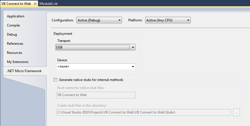
Don, Try selecting Project from the tab at the top, Select program at the bottom of the pulldown menu, then select Micro Framework page. Change to serial transport then back to USB. Don't know why but it worked for me. Chuck Attached Thumbnails#38858 Reading 1 Wire Digital Temp Sensor
Nick, There has been some posts about one wire in the last couple of weeks that should help you. Try searching the forum for "One Wire" and "OneWire" and I am certain you will find what you are looking for. 4.2.0.0 firmware and One Wire and Netduino Plus 2 with OneWire Chuck #42557 Problem with PWM Setpulse
#35203 Netduino: Good starting point for beginners?
Daniel,
The answer lies with your girlfriends interests, if she enjoys puzzles, building thing and being creative then she most likely will enjoy using a Netduino. If she get discouraged easy when it doesn't work on the first try maybe not.
I don't know of anyone that has ever tried to build something and had it work exactly the way they wanted it too or after finishing didn't come up with something else to improve on their first effort. But for most that is the challenge.
Best bet is to get her one to try, she she doesn't like it, then you have one for yourself (you have to look for the silver linings sometimes).

#40911 Netduino Plus 2 and Adafruit RGB LCD Shield
I am currently using Neduino SDK 4.2.1. I have tried to load the toolbox sample for the Adafruit RGB LCD display on both the Netduino Classic and Netduino Plus 2.
On the Classic I get an E300000 error code and the wrong mscorlib.dll. I followed the FAQ in wiki could not change the library from 4.1 to 4.2
I then went back to the Netduino Plus 2 with firmware 4.2.1.2 loaded. The shield uses I2C and ties Analog Pins 4 & 5 to the SC & SD connection and has pullup resistors on the I2C lines.
With this setup I get errors that it can not find namespace name 'Hd44780Lcd', 'IGPIPort' or 'Mcp23017'.
I have added every reference that I can find if no luck.
If Stefan (when you get some time) or someone can give me a hint on how to fix this it would be appreciated.
Thanks,
Chuck
#41046 Need 12v monitoring
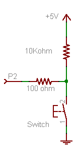
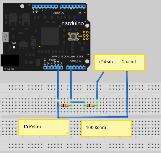
Kaya,
Welcome to the forum. A simple voltage divider should work, see the attached post Watching Voltage through Analog If you only need to see if the LED is On or Off you can use either a Analog or Digital input. You will want to drop the voltage down to < 3.3 vdc. By the way the heading says 12 volt but the text says 24 volt. If it is 12 vdc you can change the ratio of the resistors. Chuck Attached Thumbnails#41068 Need 12v monitoring
You read the voltage between the 2 resistors and ground (make sure that you are across the 10K ohm resistor or the low value of the voltage divider, across 1 resistor is 21.6 vdc the other 2.4 vdc). I reccommend reading the voltage with a voltmeter before connecting the Netduino so as not to apply more than 3.3 vdc. If you use a digital input when the io is false or for an analog when it reads 0 or < 0.05. Chuck #38838 adafruit LCD shield I2C
Glen, How are you powering the Netduino +, from the USB or the barrel connector? If you are using the USB, you maybe loading it to where the voltage is dropping to much (depending on power supply). May want to try 9vdc to barrel connector (check polarity is correct before plugging in the adapter). Also check solder joints on the LCD shield to make sure that there are no unwanted inter-connections between pins. Is the regulator chip get hot? If so that may indicate overloaded regulator. If you have an ampmeter you may be able to power the shield with male-female jumpers to read the current draw of the shield. Other than that it is difficult to help without a clear picture or information on the setup. Hope this helps, Chuck #40980 Go Socket Breakout
Baxter, I have not used the GHI breakout, so I can not say. But I can recommend the modules that Matt designed. Komodex Labs - GoBus Breakout Module They cost a little more but give you a lot more options and abilities for testing / programming. Chuck #40182 Netduino Plus 2
Bernd, I found it, finally, it was in "Introducing Netduino Plus 2 The next generation of Netduino Plus" on page 3. Chuck #40175 Netduino Plus 2
Bernd, The Netduino Plus 2 can use 12vdc to the barrel connector, but using 9vdc reduces the power that the regulator must dump. This is not a problem if the current through the regulator is reasonable, but if you are near maximum current draw for the regulator you can overheat it. At 9vdc the temperature will be less for a given current. This question was answered here on one of the thread if you want more detail. Chuck | ||||||||||||||
|
||||||||||||||
| This webpage is licensed under a Creative Commons Attribution-ShareAlike License. | ||||||||||||||