Netduino home hardware projects downloads community

Jump to content


The Netduino forums have been replaced by new forums at community.wildernesslabs.co. This site has been preserved for archival purposes only and the ability to make new accounts or posts has been turned off.

DaveRVW

Member Since 28 Dec 2010
Offline Last Active Oct 21 2016 11:28 PM
-----

#41125 More GoBus news: DIP chips for STM8S modules

Posted by DaveRVW on 07 December 2012 - 04:02 AM

Solution found for the STM8 SDIP chips. These breakout boards from SchmartBoard model # 201-0001-01 for $5 each do the trick. These boards are 0.1" spacing rows, but interleaved at 0.05". Sorry, they look like they are on backorder from the manufacturer, but you can probably find them in stock at your favorite electronics distributor, Fry's Electronics, etc. This board costs more than the chip, but when you've gotta have it now, it works, and is cleaner looking than dead bugging it.

If you use Pythagorean theorem on a right triangle with 0.05" sides, the hypotenuse has a side of 0.07071" which is close enough for our use (targetting 0.07"). From the first pin to the 16th pin, that's only off by about 0.01" total which is smaller than the size of a hole.

Posted Image
Posted Image

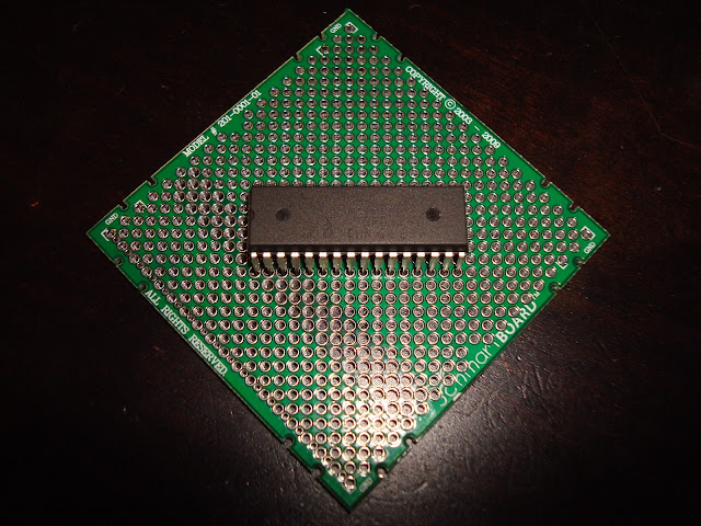
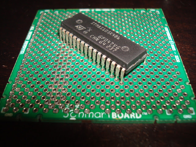
p.s. Each five consecutive pins in a row are connected, but due to the shape of the STM8 SDIP it appears that none of the cpus pins get shorted together.


#40922 Netduino Plus 2 Firmware v4.2.1 (Update 2)

Posted by DaveRVW on 04 December 2012 - 06:43 AM

Hint: when troubleshooting i2c it can be useful to put the transactional code into a loop, with a delay between iterations, so you can tweak your circuit to see if you get different results And update 2 works for me talking to Microchip 24FC1025 jumpered directly to SCL/SDA. Both running in debugger, and running standalone (USB removed, supplying external 5V power) outputing results to SerialPort.


#40462 I2C Software Workaround for Plus 2

Posted by DaveRVW on 30 November 2012 - 07:46 AM

This SoftwareI2CBus class can be used to help workaround Netduino Plus 2 I2C problems.

I was able to successfully read from my I2C EEPROM. Another advantage is that you can choose to use different pins too.

(Note this leverages a software I2C driver written by our peers over at tinyclr and GHI. Note that a portion must be downloaded from the tinyclr site (link will show when you try to compile). The value I added was to replace the custom APIs with ones more compatible with the standard I2C APIs. Known issue: read/write timeouts are either fixed or otherwise ignored.)


Good luck guys! The Netduino Plus 2 is a great platform, and hopefully this can help one or two folks that hit the early defects in I2C.

Usage comparison between hardware and software I2C:

#define I2C_SOFTWARE
#if I2C_SOFTWARE
            SoftwareI2CBus i2cbus = new SoftwareI2CBus(Pins.GPIO_PIN_A5, Pins.GPIO_PIN_A4);
            SoftwareI2CBus.I2CDevice i2c = i2cbus.CreateI2CDevice(new I2CDevice.Configuration(0x50, 400));
#endif
#if I2C_HARDWARE
            I2CDevice i2c = new I2CDevice(new I2CDevice.Configuration(0x50, 400));
#endif

Attached Files


#30179 Serial port deployment

Posted by DaveRVW on 04 June 2012 - 03:24 PM

I just took a better look at your attached photos, and oops... The 232 lines should not usually be connected directly to the Netduino as they may have more voltage than can be accepted. The 232 spec allows for signals in the range 3V-15V whereas the Netduino is expecting 3.3V, but tolerant of 5V signals. Maybe the Netduino isn't damaged because often these adapters use voltages in the lower ranges. You should use a TTL level (TTL level signals are at microprocessor voltages like 3.3V or 5V) USB adapter like one of these to connect directly to the Netduino (either 5V or 3.3V are okay): http://www.sparkfun.com/products/9718 http://www.sparkfun.com/products/9873 (there are lots more out there, these are just some samples)


#29833 Hardware Details: Shield Base

Posted by DaveRVW on 27 May 2012 - 04:39 PM

... created a prototype shield for the shield base to do all the wiring from FTDI cable with 3.3V regulator. That worked too. I can share that later.


Plugging this into the shield base by itself, and plugging FTDI Cable 5V into the six pin right angle jack, this provides power and access to the 512K shield base via USB to serial. This way the 512K shield base can be used separate from the Go, as a low priced Netduino.

The 3.3V regulator is LM1117MPX-3.3/NOPB (SOT-223), with a 10uF tantalum capacitor on 5V input, and 22uF tantalum capacitor on 3.3V output. I used the freetronics prototype shield and populated it with a reset button, power LEDs, 0.1uF filter capacitors, and Arduino style headers (sorry IOREF, SCL, SDA). TX and RX from the FTDI are connected to D0 and D1 of the Netduino.

Posted Image Posted Image Posted Image
(click on pictures to see larger)


home    hardware    projects    downloads    community    where to buy    contact Copyright © 2016 Wilderness Labs Inc.  |  Legal   |   CC BY-SA
This webpage is licensed under a Creative Commons Attribution-ShareAlike License.