Netduino home hardware projects downloads community

Jump to content


The Netduino forums have been replaced by new forums at community.wildernesslabs.co. This site has been preserved for archival purposes only and the ability to make new accounts or posts has been turned off.
Photo

Embarassing SPI question (re: Netduino Helper Max72197221.cs )


  • Please log in to reply
28 replies to this topic

#21 hanzibal

hanzibal

    Advanced Member

  • Members
  • PipPipPip
  • 1287 posts
  • LocationSweden

Posted 05 September 2013 - 10:22 AM

When cascaded like this, the chips collectively form a big shift register with a bit length equal to 16 x the number of chips. As long as you keep LOAD low, bits are just shifted through according to the number of clock cycles. You can think of the data bits as a train running on a track through a series of stations where each of them corresponds to the cascaded chips respectively. The clock is your train engine and when you stop the engine, the train stops and the passengers (the bits) arrive to the location where they happen to be when the train stopped. You then open the doors by raising LOAD to let the passengers off. As for your questions:


1. The above should answer that

2. Yes but it's only necessary to raise LOAD when bits are in place

3. I've never used the emulator so I wouldn't know but an external device generally cannot tell the difference if it's being bit banged or communicating with a an actual hardware peripheral (e.g. h/w SPI)

4. Yes, only one LOAD when bits have arrived to the designated chip (see 3)


I wouldn't know about power consumption.


#22 Emilio x64

Emilio x64

    Advanced Member

  • Members
  • PipPipPip
  • 40 posts

Posted 05 September 2013 - 02:57 PM

Thanks for the clarification, I will change my firmware, I guess you recommed doing the Chip Select (SS) manually rather than letting the .NET Microframework's SPI software do it, right?


By emulation I meant the .NET Extensible Emulator where you create a user interface to mimick your device. That's what I did, created a winform to mimick the faceplate of my device where I could interact with buttons (pushbuttons and a dual concentric encoder) as well as a separate winform that would show me in real time the current state of all registers of the "emulated" MAX7219.


#23 hanzibal

hanzibal

    Advanced Member

  • Members
  • PipPipPip
  • 1287 posts
  • LocationSweden

Posted 06 September 2013 - 10:31 AM

Yes so it seems.


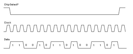
...however, when come to think of it again, I'm not sure h/w SPI is supposed to raise !CS until the bit stream has been sent in full (e.g. !CS keps low in between individual bytes) but according to this image it does briefly:

Posted Image


Whereas in this picture it does not:

Posted Image


I'll have to look in my scope to see exactly how SPI behaves (or misbehaves) on the Netduino.


Interesting info about the emulator, I was unaware of there being such a thing with hardware models. Is it part of Visual Studio or do you have to download it explicitly - if so from where?


Is the [color=rgb(40,40,40);font-family:helvetica, arial, sans-serif;]MAX7219 mimic part of the emulator or did you write and add that yourself?[/color]


#24 Emilio x64

Emilio x64

    Advanced Member

  • Members
  • PipPipPip
  • 40 posts

Posted 11 September 2013 - 05:12 PM

The "Microsoft Extensible Emulator" is part of the Visual Studio IDE AFAIK. But it is great in allowing you to mimick your end device when you still don't have hardware (I have a design but I am testing some concepts).


The MAX7219 emulator code I wrote myself because I wanted to see the state of the chip during debugging (just as if I had a real emulator pOD on a real device) but I have to fix it based on your comments (the NoOp). However, it goes only as far as keeping track of the register values, state and notifying the UI to update the UI accordingly. It does not include a real 7-segment emulator that would ideally read the status of the A-G,DP segment output pins and display accordingly. Perhaps some day I add it, in the meantimeI have to fix the emulator code and find some suppliers for my 7-segment displays


#25 vader7071

vader7071

    Advanced Member

  • Members
  • PipPipPip
  • 132 posts
  • LocationDothan, AL

Posted 26 November 2013 - 08:32 PM

I have a question on this topic.  I went and found the code from Netduino Helper you referenced in the beginning, but when I loaded it, I am getting an error:


"Error 1 The type or namespace name 'ExtendedSpiConfiguration' could not be found (are you missing a using directive or an assembly reference?) C:UserscwrenDocumentsVisual Studio 2012ProjectsMax7219-7221Max7219-7221Program.cs 99 41 Max7219-7221"


I double clicked on this and it created an addition file in the solution listing (using Visual Studio Pro 2012) titled "ExtendedSpiConfiguration" but I wasn't sure what I needed to do with it.


In a short run, I am wanting to control 2 separate LED matrix, one 5x7 and one 5x6.  I will also want to control another matrix about 5x40.  The goal is complete and total random flashing of the LEDs.


This is the section of the code where I get the error.


public Max72197221(Cpu.Pin chipSelect, SPI.SPI_module spiModule = SPI.SPI_module.SPI1, uint speedKHz = (uint)10000)
        {
            var extendedSpiConfig = new ExtendedSpiConfiguration(
                SPI_mod: spiModule,
                ChipSelect_Port: chipSelect,
                ChipSelect_ActiveState: false,
                ChipSelect_SetupTime: 0,
                ChipSelect_HoldTime: 0,
                Clock_IdleState: false,
                Clock_Edge: true,
                Clock_RateKHz: speedKHz,
                BitsPerTransfer: 16);
 
            Spi = new SPI(extendedSpiConfig);
 
            DigitScanLimitSafety = true;
 
            SpiBuffer = new ushort[1];
        }


#26 vader7071

vader7071

    Advanced Member

  • Members
  • PipPipPip
  • 132 posts
  • LocationDothan, AL

Posted 07 December 2013 - 07:34 PM

I went back and found the cs file cs file called "ExtendedSpiConfiguration.cs" but how do I get the proram file to link to the additional cs file?


#27 vader7071

vader7071

    Advanced Member

  • Members
  • PipPipPip
  • 132 posts
  • LocationDothan, AL

Posted 07 December 2013 - 09:09 PM

Figured out part of my issue.


I right clicked on the solution name (in Visual Studio Pro 2012) and clicked "Add Existing Item" and then selected the extendedspiconfiguration.cs file, and that made my error go away.


#28 vader7071

vader7071

    Advanced Member

  • Members
  • PipPipPip
  • 132 posts
  • LocationDothan, AL

Posted 20 December 2013 - 04:03 PM

I got the program loaded, and was able to get my hands on a few of the 8x8 led matrix and MAX7219 chip protoboards.


I loaded the program into the Netduino, but ran into an issue.  The error I got was:


Error 1 Program 'c:UserscwrenDocumentsVisual Studio 2012ProjectsMax7219-7221Max7219-7221objDebugMax7219-7221.exe' does not contain a static 'Main' method suitable for an entry point C:Userscwrendocumentsvisual studio 2012ProjectsMax7219-7221Max7219-7221CSC Max7219-7221
 
 
And reading the error and thinking on it, it looks like the file I downloaded (max72197221.cs) is supposed to be a secondary file that is called from a main file.  This is outside of my understanding.  Is there a tutorial where I can learn on how to make this work?


#29 hanzibal

hanzibal

    Advanced Member

  • Members
  • PipPipPip
  • 1287 posts
  • LocationSweden

Posted 10 January 2014 - 08:41 PM

Make sure you got a class called "Program" implementing a static method void Main() - that method is your application entry point and will be called when the run time environment is ready to launch your application.


0 user(s) are reading this topic

0 members, 0 guests, 0 anonymous users

home    hardware    projects    downloads    community    where to buy    contact Copyright © 2016 Wilderness Labs Inc.  |  Legal   |   CC BY-SA
This webpage is licensed under a Creative Commons Attribution-ShareAlike License.