Analog Input Example on the Netduino Plus and Netduino Plus 2 - Netduino Plus 2 (and Netduino Plus 1) - Netduino Forums
   
Netduino home hardware projects downloads community

Jump to content


The Netduino forums have been replaced by new forums at community.wildernesslabs.co. This site has been preserved for archival purposes only and the ability to make new accounts or posts has been turned off.
Photo

Analog Input Example on the Netduino Plus and Netduino Plus 2


  • Please log in to reply
9 replies to this topic

#1 cutlass

cutlass

    Advanced Member

  • Members
  • PipPipPip
  • 78 posts
  • LocationNew England. :)

Posted 16 March 2013 - 01:38 AM

There have been a few question on how to use analog inputs on the Netduino Plus and Netduino Plus 2.

I hope the following two posts help to clear up some questions.


Post#2 in this thread will have an example using the:  Netduino Plus.

Post#3 in this thread will have an example using the: Netduino Plus 2.


For each board, I also added a zip of the project and files.

Good Luck!  


#2 cutlass

cutlass

    Advanced Member

  • Members
  • PipPipPip
  • 78 posts
  • LocationNew England. :)

Posted 16 March 2013 - 01:39 AM

Netduino Plus Example:


Uses .NET  Micro Framework 4.1


Code:

using System;using System.Net;using System.Net.Sockets;using System.Threading;using Microsoft.SPOT;using Microsoft.SPOT.Hardware;using SecretLabs.NETMF.Hardware;using SecretLabs.NETMF.Hardware.NetduinoPlus;namespace AnalogTest {    public class Program {	    private const int MaximumValue_int = 1024;	    private const float AnalogReference_float = 3.30f;	    private const float VoltsPerCount_float = AnalogReference_float / MaximumValue_int;	    public static void Main() {		    // Define and initialize variables		    int ADC_digitalValueRead_int = 0;		    float ADC_analogValueConverted_float = 0;		    int ADC_digitalValueRead0_int = 0;		    int ADC_digitalValueRead1_int = 0;		    int ADC_digitalValueRead2_int = 0;		    int ADC_digitalValueRead3_int = 0;		    int ADC_digitalValueReadSum_int = 0;		    int ADC_digitalValueReadAverage_int = 0;		    float ADC_analogValueAverageConverted_float = 0;		    SecretLabs.NETMF.Hardware.AnalogInput adcPort_A0 = new SecretLabs.NETMF.Hardware.AnalogInput(Pins.GPIO_PIN_A0);		    //init the values		    ADC_digitalValueRead_int = adcPort_A0.Read();		    ADC_digitalValueRead0_int = ADC_digitalValueRead_int;		    ADC_digitalValueRead1_int = ADC_digitalValueRead_int;		    ADC_digitalValueRead2_int = ADC_digitalValueRead_int;		    ADC_digitalValueRead3_int = ADC_digitalValueRead_int;		    ADC_digitalValueReadAverage_int = 0;		    // do forever...		    while (true) {			    // read from ADC Port_A0			    ADC_digitalValueRead_int = adcPort_A0.Read();			    // convert digital value to analog voltage			    ADC_analogValueConverted_float = ((float)ADC_digitalValueRead_int) * VoltsPerCount_float;			    // Print the values in the debug window			    Debug.Print("Raw Value: " + ADC_digitalValueRead_int.ToString() +						    "  ; Volts: " + ADC_analogValueConverted_float.ToString());			    // Slightly more advanced, simple average of the last four ADC values.			    // Shift values, sum, and average			    ADC_digitalValueRead0_int = ADC_digitalValueRead1_int;			    ADC_digitalValueRead1_int = ADC_digitalValueRead2_int;			    ADC_digitalValueRead2_int = ADC_digitalValueRead3_int;			    ADC_digitalValueRead3_int = ADC_digitalValueRead_int;			    ADC_digitalValueReadSum_int = ADC_digitalValueRead0_int + ADC_digitalValueRead1_int + ADC_digitalValueRead2_int + ADC_digitalValueRead3_int;			    ADC_digitalValueReadAverage_int = ADC_digitalValueReadSum_int >> 2;  // ADC_digitalValueReadSum_int = (ADC_digitalValueReadSum_int/4);			    // convert digital value to analog voltage			    ADC_analogValueAverageConverted_float = ((float)ADC_digitalValueReadAverage_int) * VoltsPerCount_float;			    // Print the values in the debug window			    Debug.Print("Averaged Value: " + ADC_digitalValueReadAverage_int.ToString() +						    "    ; Averaged Volts: " + ADC_analogValueAverageConverted_float.ToString());			    Debug.Print(" ");		    }	    }    }}


Example Output:

Raw Value: 430  ; Volts: 1.38574219 Averaged Value: 427   ; Averaged Volts: 1.37607419 Raw Value: 431  ; Volts: 1.38896477 Averaged Value: 429   ; Averaged Volts: 1.38251948 Raw Value: 428  ; Volts: 1.3792969 Averaged Value: 430   ; Averaged Volts: 1.38574219 Raw Value: 430  ; Volts: 1.38574219 Averaged Value: 429   ; Averaged Volts: 1.38251948 Raw Value: 425  ; Volts: 1.36962891 Averaged Value: 428   ; Averaged Volts: 1.3792969 Raw Value: 427  ; Volts: 1.37607419 Averaged Value: 427   ; Averaged Volts: 1.37607419 Raw Value: 434  ; Volts: 1.39863276 Averaged Value: 429   ; Averaged Volts: 1.38251948 Raw Value: 431  ; Volts: 1.38896477 Averaged Value: 429   ; Averaged Volts: 1.38251948 Raw Value: 433  ; Volts: 1.39541018 Averaged Value: 431   ; Averaged Volts: 1.38896477 Raw Value: 431  ; Volts: 1.38896477 Averaged Value: 432   ; Averaged Volts: 1.39218748 Raw Value: 430  ; Volts: 1.38574219 Averaged Value: 431   ; Averaged Volts: 1.38896477 Raw Value: 432  ; Volts: 1.39218748 Averaged Value: 431   ; Averaged Volts: 1.38896477 Raw Value: 428  ; Volts: 1.3792969 Averaged Value: 430   ; Averaged Volts: 1.38574219 Raw Value: 430  ; Volts: 1.38574219 Averaged Value: 430   ; Averaged Volts: 1.38574219 Raw Value: 432  ; Volts: 1.39218748 Averaged Value: 430   ; Averaged Volts: 1.38574219 Raw Value: 426  ; Volts: 1.37285149 Averaged Value: 429   ; Averaged Volts: 1.38251948 Raw Value: 431  ; Volts: 1.38896477 Averaged Value: 429   ; Averaged Volts: 1.38251948 Raw Value: 436  ; Volts: 1.40507805 Averaged Value: 431   ; Averaged Volts: 1.38896477 Raw Value: 430  ; Volts: 1.38574219 Averaged Value: 430   ; Averaged Volts: 1.38574219 Raw Value: 432  ; Volts: 1.39218748 Averaged Value: 432   ; Averaged Volts: 1.39218748 Attached File  N+AnalogInput.zip   88.62KB   91 downloads


#3 cutlass

cutlass

    Advanced Member

  • Members
  • PipPipPip
  • 78 posts
  • LocationNew England. :)

Posted 16 March 2013 - 01:39 AM

Netduino Plus2 Example:


Uses .NET  Micro Framework 4.2


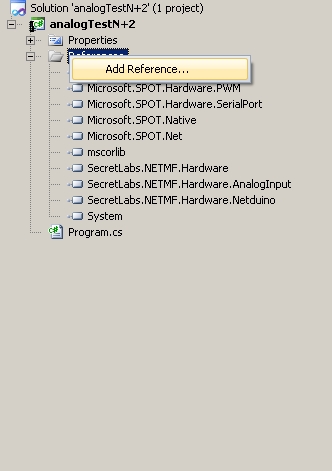
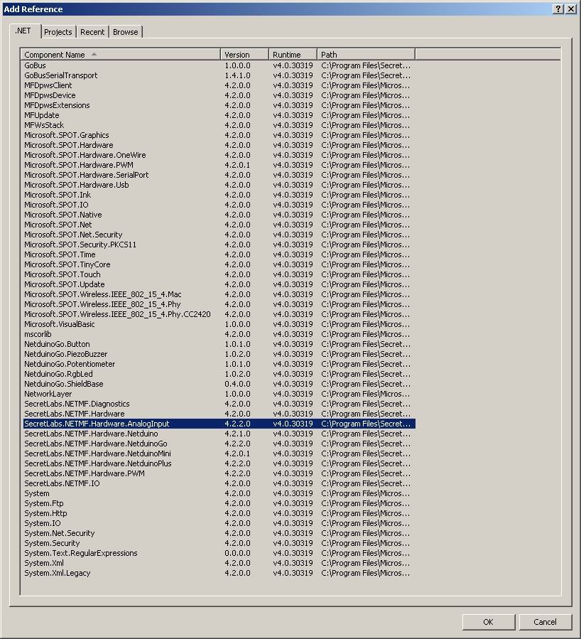
You should add a reference to the SecretLabs.NETMF.Hardware.AnalogInput dll.


Right Click on References

Posted Image


Select "SecretLabs.NETMF.Hardware.AnalogInput"

Posted Image


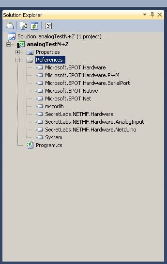
Your References List should now include"SecretLabs.NETMF.Hardware.AnalogInput":

Posted Image


Code:

using System;using System.Net;using System.Net.Sockets;using System.Threading;using Microsoft.SPOT;using Microsoft.SPOT.Hardware;using SecretLabs.NETMF.Hardware;using SecretLabs.NETMF.Hardware.Netduino;namespace AnalogTest {    public class Program {        private const int MaximumValue_int = 1024;        private const float AnalogReference_float = 3.30f;        private const float VoltsPerCount_float = AnalogReference_float / MaximumValue_int;        public static void Main() {            // Define and initialize variables            int ADC_digitalValueRead_int = 0;            float ADC_analogValueConverted_float = 0;            int ADC_digitalValueRead0_int = 0;            int ADC_digitalValueRead1_int = 0;            int ADC_digitalValueRead2_int = 0;            int ADC_digitalValueRead3_int = 0;            int ADC_digitalValueReadSum_int = 0;            int ADC_digitalValueReadAverage_int = 0;            float ADC_analogValueAverageConverted_float = 0;            SecretLabs.NETMF.Hardware.AnalogInput adcPort_A0 = new SecretLabs.NETMF.Hardware.AnalogInput(Pins.GPIO_PIN_A0);            //init the values            ADC_digitalValueRead_int = adcPort_A0.Read();            ADC_digitalValueRead0_int = ADC_digitalValueRead_int;            ADC_digitalValueRead1_int = ADC_digitalValueRead_int;            ADC_digitalValueRead2_int = ADC_digitalValueRead_int;            ADC_digitalValueRead3_int = ADC_digitalValueRead_int;            ADC_digitalValueReadAverage_int = 0;            // do forever...            while (true) {                // read from ADC Port_A0                ADC_digitalValueRead_int = adcPort_A0.Read();                // convert digital value to analog voltage                ADC_analogValueConverted_float = ((float)ADC_digitalValueRead_int) * VoltsPerCount_float;                // Print the values in the debug window                Debug.Print("Raw Value: " + ADC_digitalValueRead_int.ToString() +                            "  ; Volts: " + ADC_analogValueConverted_float.ToString());                // Slightly more advanced, simple average of the last four ADC values.                // Shift values, sum, and average                ADC_digitalValueRead0_int = ADC_digitalValueRead1_int;                ADC_digitalValueRead1_int = ADC_digitalValueRead2_int;                ADC_digitalValueRead2_int = ADC_digitalValueRead3_int;                ADC_digitalValueRead3_int = ADC_digitalValueRead_int;                ADC_digitalValueReadSum_int = ADC_digitalValueRead0_int + ADC_digitalValueRead1_int + ADC_digitalValueRead2_int + ADC_digitalValueRead3_int;                ADC_digitalValueReadAverage_int = ADC_digitalValueReadSum_int >> 2;  // ADC_digitalValueReadSum_int = (ADC_digitalValueReadSum_int/4);                // convert digital value to analog voltage                ADC_analogValueAverageConverted_float = ((float)ADC_digitalValueReadAverage_int) * VoltsPerCount_float;                // Print the values in the debug window                Debug.Print("Averaged Value: " + ADC_digitalValueReadAverage_int.ToString() +                            "    ; Averaged Volts: " + ADC_analogValueAverageConverted_float.ToString());                Debug.Print(" ");            }        }    }}


Example Output:

Raw Value: 427  ; Volts: 1.37607419
Averaged Value: 425   ; Averaged Volts: 1.36962891

Raw Value: 423  ; Volts: 1.36318362
Averaged Value: 425   ; Averaged Volts: 1.36962891

Raw Value: 423  ; Volts: 1.36318362
Averaged Value: 424   ; Averaged Volts: 1.3664062

Raw Value: 424  ; Volts: 1.3664062
Averaged Value: 424   ; Averaged Volts: 1.3664062

Raw Value: 421  ; Volts: 1.35673821
Averaged Value: 422   ; Averaged Volts: 1.35996091

Raw Value: 420  ; Volts: 1.35351562
Averaged Value: 422   ; Averaged Volts: 1.35996091

Raw Value: 427  ; Volts: 1.37607419
Averaged Value: 423   ; Averaged Volts: 1.36318362

Raw Value: 430  ; Volts: 1.38574219
Averaged Value: 424   ; Averaged Volts: 1.3664062

Raw Value: 424  ; Volts: 1.3664062
Averaged Value: 425   ; Averaged Volts: 1.36962891

Raw Value: 424  ; Volts: 1.3664062
Averaged Value: 426   ; Averaged Volts: 1.37285149

Raw Value: 423  ; Volts: 1.36318362
Averaged Value: 425   ; Averaged Volts: 1.36962891

Raw Value: 429  ; Volts: 1.38251948
Averaged Value: 425   ; Averaged Volts: 1.36962891

Raw Value: 425  ; Volts: 1.36962891
Averaged Value: 425   ; Averaged Volts: 1.36962891

Raw Value: 425  ; Volts: 1.36962891
Averaged Value: 425   ; Averaged Volts: 1.36962891

Raw Value: 428  ; Volts: 1.3792969
Averaged Value: 426   ; Averaged Volts: 1.37285149

Raw Value: 422  ; Volts: 1.35996091
Averaged Value: 425   ; Averaged Volts: 1.36962891

Raw Value: 423  ; Volts: 1.36318362
Averaged Value: 424   ; Averaged Volts: 1.3664062

Raw Value: 424  ; Volts: 1.3664062
Averaged Value: 424   ; Averaged Volts: 1.3664062

Raw Value: 425  ; Volts: 1.36962891
Averaged Value: 423   ; Averaged Volts: 1.36318362

Raw Value: 427  ; Volts: 1.37607419
Averaged Value: 424   ; Averaged Volts: 1.3664062

Attached File  analogTestN+2.zip   56.29KB   121 downloads


#4 cutlass

cutlass

    Advanced Member

  • Members
  • PipPipPip
  • 78 posts
  • LocationNew England. :)

Posted 16 March 2013 - 01:59 AM

.

Some notes:


Putting much over 3.3v on the analog input will FRY the chip!
My Netduino Plus2 died when I accidentally went to ~4V.   I turned the course adjust by mistake instead of the fine adjust on the power supply.

Also, it's a very good idea to put an ~100Ohm to 1K resistor inline with the ADC input to limit the current into the chip if input does have a slight overshoot over ~3.3v.

Note that for signals from another device, there could be overshoot and undershoot for some short period of time.  Especially if connected by a wire.  It depends on the rate of change of the input signal, and the impedances of the signal,wire, and input stage.


I had two Netduino Plus2 boards and two Netduino Plus1 boards.

I still do. :)  But, one of the Netduino Plus2 no longer works.  And, the ARM SOC gets very hot as soon as I power the board.

For sale: One slightly used Netduino Plus2 board. ;)


From the thread:

http://forums.netdui...n-on-tolerance/


Summary:

When a pin is in ADC mode (PC0-PC5 ; pins 8,9,10,11, 24,25), the voltage limits are as follows:

Low: -0.3v

High: +3.6v (3.3v + 0.3v)


The data sheet is here:

http://www.st.com/st.../DM00037051.pdf


The N+2 uses a 64pin STM32F405RG


From the data sheet:


ADC voltage input specs:

page: 105:

VIL Input low level voltage

Min Vin Low

VIL VSS–0.3v

(VSS is ground.  So, the minimum voltage is -0.3v)


Max Vin High
VIH TTa/TC(2) I/O input high level voltage  VDD+0.3

See Note2

2.TTa = 3.3V tolerant I/O directly connected to ADC; TC = standard 3.3V I/O.


ADC Characteristics:

Table 67

pages: 124,125


ADC equivalent input schematic:

page: 127


Good Luck!


The correct way to do the counts to volts conversion is shown in the code.

The ADCs in these SOC micros are noisy and the specs are semi-joke.  See the manuals for the details.  The amount of noise on the ADCs is horrible.

The lower 3 bits (approximately 6 counts) are mostly noise.


Note: Having 3 -> 10+ counts of noise is true for most ADCs on most SOC (systems on a chip).

If you need "good" accuracy, always check the noise, accuracy, linearity, etc.

The ADCs on these low-cost SOCs will vary by temperature, power supply, ground noise, etc.

You can characterize the ADC of a specific chip with a good low-cost precision voltage source like: HP6112A.  Check ebay.

You can then use the curve fit method of your choice.  Excel offers a line fit function.  And, the similar program from Open Office likely also has a similar function.

Again, realize that the ADC linearity, scaling, and noise will change with temperature.  However, often very noticeably improvements in the accuracy of the ADC are obtained by doing a curve fit for each device, and doing a 4 or 8-sample average .  Also, the ADCs of chips per batch often track closely.  Check the date and batch code.


I've had my HP6612A for over 10 years. IMHO, it's essential when I want to get an good idea of how accurate/stable an ADC, and/or board is.  Of course, at work, we have much much better precision voltage source supplies.  But, IMHO, the HP6112A is fine to check the vast majority of ADCs/ DVMs/ Scopes/ etc. And, I don't have to program/enable the voltage each time. :)


IMHO, at the very least, an average of 4 samples should be done if any sort of consistent value is desired.


I did my testing with a very quite lab power supply, and had the NP1 and NP2 running off a battery powering the board.  (BTW, Amazon has many rechargeable USB/etc battery packs.)

Although, some noise may have been introduced through the USB connection.  My USB connection is through a powered Belkin USB2.0 hub.  So, it should be pretty quite.


I have a tendency to write my code wordy, and to make sure that there are not any "false" assumptions about the variables/etc.

Since I do a lot of Verilog FPGA code, I hate it when I read some garbage like the following:

New_value = Value1 + Value2 + Value3;


In reality, you have no idea what the above does.  The variables may be bit vectors of different lengths, or single bits.

For C code, I believe in putting the variables type as postfix.  I use a modified, but very close, version of the accepted prefix or postfix indications of the variable type.


The above code is more explicit in the postfix to make it very easy to understand what's going on in each line.


I have a tendency to be more of a "pain" when it comes coding style and very easy readability.  A lot of that has to do with the fact that I taught Computer Engineering programming classes for Freshmen, Sophomores, and Juniors for many semesters when I was in grad school.


And, yes, I know my style above is the old style (from K&R) in some ways.  There are personal style choices. :)

For "C" and embedded programming, I prefer the explicit defines at the start, and keeping variable definitions/etc out of the main code. 


I hope the above helps.

Good Luck!


#5 sebswed

sebswed

    Advanced Member

  • Members
  • PipPipPip
  • 45 posts
  • LocationSweden

Posted 07 April 2013 - 08:45 PM

Hello Cutlass I did not know the input voltage was so critical. My first thoughts on reading your post was maybe I should use a 3.3v zener diode (1N746) to protect the input from receiving more than 3.3v before I'm going to read analog data.


Netduino Plus 2 (v4.2.2.2)


#6 cutlass

cutlass

    Advanced Member

  • Members
  • PipPipPip
  • 78 posts
  • LocationNew England. :)

Posted 02 May 2013 - 05:03 AM

Hello Cutlass

I did not know the input voltage was so critical. My first thoughts on reading your post was maybe I should use a 3.3v zener diode (1N746) to protect the input from receiving more than 3.3v before I'm going to read analog data.


Hi.  Sorry I missed your post.  I sometimes can go over a week without checking the forums.

Yes, when the N2/N2P has a pin in analog input mode, you need to make sure voltage does not exceed ~3.5V.  A zener can work. 


Many zeners have a tolerance of 10%.  I'd suggest using one with a tolerance of 5%.  Also, put an ~2.2K resistor inline of the analog input before the zener.

Similar to the image below:

Posted Image


#7 Fahdil

Fahdil

    Advanced Member

  • Members
  • PipPipPip
  • 59 posts
  • LocationJakarta, Indonesia

Posted 02 September 2013 - 02:19 AM

cool..... class works fine....


a little bit modif....


Using the class:

            AnalogInput A0 = new AnalogInput(Pins.GPIO_PIN_A0);            ADC.Conversion Temp;                  Temp = new ADC.Conversion(A0.Read());            DataStorage Log = new DataStorage("testFile.csv", "testPath");                                    while (true)            {                                    Temp.analogread(A0.Read());            //Log.ContentFile = Contain.MovingAverage(Temp.miliVolts).ToString("F");            if (Log.Write())            {                Debug.Print( Temp.miliVolts.ToString("F");            }            else { Debug.Print("Write Data Error"); }                        Thread.Sleep(10000);            }

Attached Files

  • Attached File  ADC.cs   1.59KB   95 downloads


#8 Fahdil

Fahdil

    Advanced Member

  • Members
  • PipPipPip
  • 59 posts
  • LocationJakarta, Indonesia

Posted 31 January 2014 - 09:43 PM

Hi guys,


I've got inaccurate analog reads. 

in my multimeter the the sensor output is ~280mv but the netduino always read the value as 319mv. 


I'm using LM35 as the sensor. so 319 mv = 31.9C. it's to far from 28C


now I'm force to add an offset = -40.21 mv to get close enough to actual value.


do someone ever experience this? any suggestion?


cheers


#9 Fahdil

Fahdil

    Advanced Member

  • Members
  • PipPipPip
  • 59 posts
  • LocationJakarta, Indonesia

Posted 02 February 2014 - 07:41 AM

After adding a 200k resistor. the ofset become 0.64 - 0.93 mv 


did someone know how to stabilize the analog read? (remove the noise)


cheers


#10 tonycampbell

tonycampbell

    New Member

  • Members
  • Pip
  • 2 posts

Posted 08 March 2014 - 09:28 PM

Hi Cutlass,


You have used 1024 (10 bits) as MaximumValue_int. I understand the ADCs are 12 bit (4096) and default to 12 bit if the bit resolution is not specified??


Kind Regards

TC


0 user(s) are reading this topic

0 members, 0 guests, 0 anonymous users

home    hardware    projects    downloads    community    where to buy    contact Copyright © 2016 Wilderness Labs Inc.  |  Legal   |   CC BY-SA
This webpage is licensed under a Creative Commons Attribution-ShareAlike License.