I think the initial blip might be because the netduino's outputs start on HIGH then go back to LOW. The animations look better I think, easier to follow. nicely done.Replaced the video with a new version. I found a significant error in my wiring of the cathodes for the LEDs...which would have caused some irregularities in the animations in the original video. All fixed now. Added a new startup animation, though I'm still trying to figure out how to get rid of that initial blip of light before the animation.

TRON Identity Disc by Harford Hackerspace
Started by Chris Walker, Dec 13 2010 10:25 PM
28 replies to this topic
#21

Omar (OZ)
-

- Members
-

- 564 posts
Advanced Member
Posted 17 January 2011 - 04:57 PM
#22
Thor
-

- Members
-
- 24 posts
Member
Posted 18 January 2011 - 03:39 PM
I think the initial blip might be because the netduino's outputs start on HIGH then go back to LOW. The animations look better I think, easier to follow. nicely done.
Yeah I guess that would explain it. I'll just have to tweak how that starting animation works to make it look a bit better.
Couple of additions last night:
1. created an external port for the programming connection. That way I can hook up USB and work on the code without opening the disc up.
2. installed another small switch right where the "O" is in the markings for the original power switch. I'm going to implement a mode system that allows two different modes. The first mode is the standard mode with all the animations, the second mode is used to present a more movie accurate version of the disc.
Any external ports I'm restricting to the backside of the inner ring, where the original power switch was located. This is just so I can keep external stuff kind of hidden.
Also started working on the charger last night. I didn't do anything more than layout the components on the PCB. I just wanted to get that done as it seems the battery juice is running out, so I'm in need of a charger. The disc no longer powers on just by itself, it requires a connection to the computer to be able to fire up. That puzzles me a bit since the USB connection doesn't actually provide any power as far as I know. It could provide 5V if I wanted to hook that pin up, but I haven't yet. The only pins used on the breakout board are Ground, DTR, and the TX/RX lines. As far as I know, the DTR line just provides a method of resetting the Netduino when new code is being uploaded to it.
Here's a layout of the two halves:
Front Half:
All LEDs
LED Driver
Netduino Mini
Back Half:
2 Lithium Polymer Batteries
Charge Detection Circuit with charging pads
Toggle switch for main power
Momentary switch for animation changes
Toggle switch for mode changes (SPDT On-On Switch)
External connector for Programming interface
Connections between the two halves (connections are made near the momentary button):
1: Primary interface (minimum connection required to operate the disc)
Momentary Button +
Momentary button -
Ground
Main Power
vDetect
2: Programming Interface
DTR
RX
TX
Ground
There is probably going to be one additional connection as a result of adding that small toggle switch for the mode changes. I need to provide a 5V source (the source for 5V comes from the Netduino mini board) and the two signaling lines for the switch.
I'm going to hold off doing any soldering on the charger circuit until I get my new soldering iron. I've had it with the Radio Shack specials I keep buying, so I invested in a better quality soldering iron that should last quite a bit longer. The iron I'm getting is a Hakko 936.
Edit: posted 3 more pictures from my recent work. Set the charging pins for the charging circuit in place during lunch today. They look rough, but they work, I tested the continuity with my multimeter so they should provide a charge.
#23
Thor
-
- Members
-
- 24 posts
Member
Posted 21 January 2011 - 06:49 AM
Ok so I got the charger done. Posted a few more pics of that. Just before getting that done though, the disc started acting weird, not turning on except when hooked up to my computer via USB. I tried everything I could to figure it out, but nothing seemed to correct it. One thing that I noticed was that the charge detection circuit seemed to be completely inoperative. The LED didn't light to indicate a charge, and the animation didn't change to the fade to indicate the Netduino Mini knew it was charging (via vDetect). So I decided to redo the charge detection circuit. I cleaned it up from what it was before and compressed the size of it a bit. I just have to fashion the charging pads and hook those up to the circuit to finish it up. I tested the disc after finishing the primary wiring (everything except for the charging pads) and the disc is now working properly, turning on like it should. So tomorrow night or sometime this weekend I'll finish up the charging pads and test to see if the charging system works.
I do know that my charger works, as it's outputting a steady 8.4V. I also know that the pins I'm using to make the connection are good...I got those off of an old cordless phone from it's charging base.
#24
Thor
-
- Members
-
- 24 posts
Member
Posted 24 January 2011 - 09:08 AM
Ok so I got the charger done. Posted a few more pics of that. Just before getting that done though, the disc started acting weird, not turning on except when hooked up to my computer via USB. I tried everything I could to figure it out, but nothing seemed to correct it. One thing that I noticed was that the charge detection circuit seemed to be completely inoperative. The LED didn't light to indicate a charge, and the animation didn't change to the fade to indicate the Netduino Mini knew it was charging (via vDetect). So I decided to redo the charge detection circuit. I cleaned it up from what it was before and compressed the size of it a bit. I just have to fashion the charging pads and hook those up to the circuit to finish it up. I tested the disc after finishing the primary wiring (everything except for the charging pads) and the disc is now working properly, turning on like it should. So tomorrow night or sometime this weekend I'll finish up the charging pads and test to see if the charging system works.
I do know that my charger works, as it's outputting a steady 8.4V. I also know that the pins I'm using to make the connection are good...I got those off of an old cordless phone from it's charging base.
I narrowed down the problem causing the disc not to turn on when switched on...the wires leading to the programming interface plugin seem to be affecting the disc so that it doesn't turn on. When those wires aren't plugged in, it turns on fine. I checked those wires thoroughly for shorts or anything else out of the ordinary. I even replaced the wires all the way up to the connector, but nothing I could do would stop that from happening. The next step with that is replacing the connector, but I'm waiting on parts for that. It has to be a short of some kind, because those wires are essentially dead wires when the FTDI Breakout board and USB aren't plugged in. They're just sitting there awaiting the connection, that doesn't stop them from screwing over the disc though. In the end, I could make it work without those wires, it's just more of a pita to program the disc without that connection.
Aside from that, the disc is working like it's supposed to, though I do have some issues to sort out with the programming, the animations don't quite work right on the new mode (vs the original animation mode). Everything with the charging dock works perfectly though, the charging light turns on, and when in animation mode it switches to the proper charging animation (fade in, fade out) (yeah I forgot about making that animation available in the new mode). When I get the issues sorted I'll probably post another video.
#25
Fred
-

- Members
-
- 302 posts
Advanced Member
- LocationUK
Posted 24 January 2011 - 01:00 PM
I had problems with the Netduino's outputs floating high on startup. In my case it operated a relay and opened my garage door. The easiest solution was a pull-down resistor to counteract the Netduino's built in pull-up one. I can't remember exactly what value I used - maybe 1k.
#26
Thor
-
- Members
-
- 24 posts
Member
Posted 24 January 2011 - 04:49 PM
I had problems with the Netduino's outputs floating high on startup. In my case it operated a relay and opened my garage door. The easiest solution was a pull-down resistor to counteract the Netduino's built in pull-up one. I can't remember exactly what value I used - maybe 1k.
Makes sense to me now that I looked into what pull resistors are. So I'd want to pull the 3 inputs into the LED driver to ground when not in use. That would ensure the inputs going to the driver are null when it turns on. Am I correct in thinking I need a separate resistor for all three?
#27
orpex
-

- Members
-
- 1 posts
New Member
Posted 03 February 2011 - 05:20 PM
Ask and ye shall receive:
Charging dock still needs to be done, but there was some juice in the batteries when I powered it up for the first time. The batteries weren't supposed to come charged, but whatever, it was a nice surprise.
Going to add LEDs to the inner ring. Also contemplating turning the second one into a white version.
I am casting the inner C and outer blades in clear polyethylene terephthalate with the same texture as the factory part if you are interested. $5 for the inner C, $15 for the blade. Blade comes with no flanges/tabs just the orientation hole.
Custom Identity Disc Mods
I wish I had gone the netduino route... but I did mine with the arduino nano instead of the netduino mini... and the coding was not fun especially since I have been doing C# for a living now...
#28
Thor
-
- Members
-
- 24 posts
Member
Posted 04 February 2011 - 07:22 PM
I am casting the inner C and outer blades in clear polyethylene terephthalate with the same texture as the factory part if you are interested. $5 for the inner C, $15 for the blade. Blade comes with no flanges/tabs just the orientation hole.
Custom Identity Disc Mods
I wish I had gone the netduino route... but I did mine with the arduino nano instead of the netduino mini... and the coding was not fun especially since I have been doing C# for a living now...
Nah, I'm sticking with the stock parts. There was always a blue tint to the glow from the Identity disc in the movie, so my hunch is that the blue blade and inner c combined with white LEDs will give about the right color glow.
I'm waiting for the parts to redo the mod (they've been stuck in the UPS and FedEx systems for a couple of days due to the Blizzard, but I should get them tonight), as I ended up frying my Netduino mini with an improper current measurement (been a while since I did a current reading with a multimeter). So I'm starting from scratch with my second identity disc and changing a few things, including the color of the LEDs from blue to white, among other things. If it turns out bad I can always swap out the blue ring I've already done.
I put up the start of my guide for this mod. It's not a complete guide, but is more a companion to the original guide, providing insight on things I learned from doing all these different versions of it. I'm trying to fill in the gaps I encountered in the original guide.
http://www.thunder-god.net/
Under the Projects Tab
or Direct Link: http://www.thunder-g...ntity-disc-mod/
#29
bpkdasbaum
-

- Members
-
- 12 posts
Member
Posted 22 October 2011 - 01:00 AM
Posted in other topic and SOLVED HERE
Also new updated schematics available + further details and links to the build
===============================
===============================
Hi,
I am in search of help with the Tron Disc Project. First of all, I don't know jack about programing or electronics, but I'm a quick learner.
I am currently following the two guides here:
Original Guide Hackerspace/Coding4fun
Thundergod Guide using netduino mini
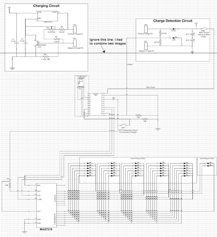
This is the basic circuit. But I would like to alter the following:
- use a premade USB charger unit like this: sparkfun micro usb charger - Data sheed with schematic here
- add more LEDs: 30 outer ring, 16 inner ring (8 on each side) and 8 for the solo lights with bezel mounts on the inner surface of the disc (4 on each side) = total of 54
The basic idea is to create the same animation as in the movie (youtube link @ scene 34 sec).
Now the questions are:
- Can I simply smolder the usb charger directly to the netduino and and attach >>both<<??? battaries onto that one charger? If yes can you please clarify how the batteries should be wired/smoldered to the usb charger?
- If I go with 54 LEDs:
- Do I need other batteries? I bought 54 x nichia 6500mcd 45° - data sheet here
- If the batteries stay the same, will my LEDs simply run out of power faster or are they going to shine less bright?
- If they shine less bright, what battery do i need?
Thanks in advance
Also new updated schematics available + further details and links to the build
===============================
===============================
Hi,
I am in search of help with the Tron Disc Project. First of all, I don't know jack about programing or electronics, but I'm a quick learner.
I am currently following the two guides here:
Original Guide Hackerspace/Coding4fun
Thundergod Guide using netduino mini
This is the basic circuit. But I would like to alter the following:
- use a premade USB charger unit like this: sparkfun micro usb charger - Data sheed with schematic here
- add more LEDs: 30 outer ring, 16 inner ring (8 on each side) and 8 for the solo lights with bezel mounts on the inner surface of the disc (4 on each side) = total of 54
The basic idea is to create the same animation as in the movie (youtube link @ scene 34 sec).
Now the questions are:
- Can I simply smolder the usb charger directly to the netduino and and attach >>both<<??? battaries onto that one charger? If yes can you please clarify how the batteries should be wired/smoldered to the usb charger?
- If I go with 54 LEDs:
- Do I need other batteries? I bought 54 x nichia 6500mcd 45° - data sheet here
- If the batteries stay the same, will my LEDs simply run out of power faster or are they going to shine less bright?
- If they shine less bright, what battery do i need?
Thanks in advance


1 user(s) are reading this topic
0 members, 1 guests, 0 anonymous users


