Running out of I/Os - Netduino Plus 2 (and Netduino Plus 1) - Netduino Forums
   
Netduino home hardware projects downloads community

Jump to content


The Netduino forums have been replaced by new forums at community.wildernesslabs.co. This site has been preserved for archival purposes only and the ability to make new accounts or posts has been turned off.
Photo

Running out of I/Os

Running out of input/outputs

  • Please log in to reply
21 replies to this topic

#1 Giuliano

Giuliano

    Advanced Member

  • Members
  • PipPipPip
  • 361 posts
  • LocationSimi Valley, CA

Posted 16 February 2013 - 05:35 AM

Good day everyone,


GoBus 1.5 is around the corner for the Go so, I was wondering what people is doing when running now when running out of I/O ports available? 


Please advise


Thanks


#2 bsilvereagle

bsilvereagle

    Member

  • Members
  • PipPip
  • 11 posts

Posted 16 February 2013 - 06:36 AM

It is a little ambitious, but you can create GoBus modules using other microprocessors as "modules". In doing this, you gain all the GPIO pins of the new microprocessor. 


I have done this with a Parallax Propeller and am also doing it with a Netduino Plus 2. Unfortunately, the code isn't public yet (it will be by April). If you are not interested in the wait and want to start writing your own drivers, don't be afraid to PM me for help. 


Also, keep in mind that every GoBus is essentially a SPI bus - if you find a SPI I/O expander you could talk directly to it over the GoBus - granted, you will have to write a custom driver and will lose the benefits of GoBus 1.5/2.0. 


Good luck!


#3 Nevyn

Nevyn

    Advanced Member

  • Members
  • PipPipPip
  • 1072 posts
  • LocationNorth Yorkshire, UK

Posted 16 February 2013 - 10:53 AM

GoBus 1.5 is around the corner for the Go so, I was wondering what people is doing when running now when running out of I/O ports available? 

I knocked a little module using 595 shift registers and an STM8S to give some extra outputs.


Regards,

Mark


To be or not to be = 0xFF


Blogging about Netduino, .NET, STM8S and STM32 and generally waffling on about life

Follow @nevynuk on Twitter


#4 Giuliano

Giuliano

    Advanced Member

  • Members
  • PipPipPip
  • 361 posts
  • LocationSimi Valley, CA

Posted 17 February 2013 - 03:41 AM

It is a little ambitious, but you can create GoBus modules using other microprocessors as "modules". In doing this, you gain all the GPIO pins of the new microprocessor. 


I have done this with a Parallax Propeller and am also doing it with a Netduino Plus 2. Unfortunately, the code isn't public yet (it will be by April). If you are not interested in the wait and want to start writing your own drivers, don't be afraid to PM me for help. 


Also, keep in mind that every GoBus is essentially a SPI bus - if you find a SPI I/O expander you could talk directly to it over the GoBus - granted, you will have to write a custom driver and will lose the benefits of GoBus 1.5/2.0. 


Good luck!


Thank you for your feedback, would this work for the N+ and N+2 as well?


#5 hanzibal

hanzibal

    Advanced Member

  • Members
  • PipPipPip
  • 1287 posts
  • LocationSweden

Posted 17 February 2013 - 03:55 AM

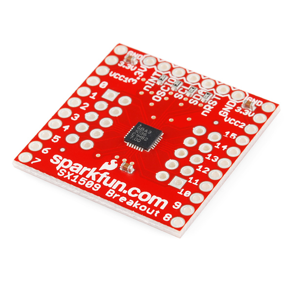
I recently picked up this 10 USD thing which gives you 16 fresh bi-directional GPIOs. Got lots of nice features too - can act as a level shifter, can strobe up to 64 pins (for keypads and such), can generate interrupts on high/low flanks of any pin.


Configuration and interfacing is done through 400kHz I2C.Posted Image

Datasheet:

http://dlnmh9ip6v2uc...ards/sx1509.pdf


#6 Giuliano

Giuliano

    Advanced Member

  • Members
  • PipPipPip
  • 361 posts
  • LocationSimi Valley, CA

Posted 17 February 2013 - 04:38 AM

Thank you hanzibal, really cool, now I need to try it out.


#7 Giuliano

Giuliano

    Advanced Member

  • Members
  • PipPipPip
  • 361 posts
  • LocationSimi Valley, CA

Posted 23 May 2013 - 04:22 PM

Good day everyone,


I never had the time to try any of the approaches recommended here in this thread but I was wondering what's available nowadays.


Also, can I use the Netduino Go Shield Base with my N+2 to expand the I/Os? If so, how?


#8 hanzibal

hanzibal

    Advanced Member

  • Members
  • PipPipPip
  • 1287 posts
  • LocationSweden

Posted 23 May 2013 - 06:41 PM

Hi!


The above SX1509 BOB from Sparkfun still stands tall I think, but there are lots of cheaper solutions as well.


It all depends on your requirements:


Do you need analogue, digital or both?

Have many pins / channels do you need?

Do you need input, output or both?

Need interrupts on input pins?


I recently came across the PCF8574 which is a quasi bi-directional I2C controlled digital only 8 bit I/O expander with interrupt capabilities. It's really simple to use, very general purpose and I've written a generic driver class for it and an I2C bus manager.


You can find the code in this post where I use it to drive a 16x2 character LCD in 4 bit parallel mode:


http://forums.netdui...-and-ir-remote/


#9 Giuliano

Giuliano

    Advanced Member

  • Members
  • PipPipPip
  • 361 posts
  • LocationSimi Valley, CA

Posted 23 May 2013 - 08:28 PM

Hi hanzibal,


Thanks for your reply.


I forgot to mention that I am running of Digital ports, I am not using any of the Analog ports, so I would definitely need at least 1 extra Digital PWN port and 1 extra Digital RX/TX, both for output only.


How dificult would it be to drive the external board to accomplish what I want?


Please advise.


Thank you


#10 hanzibal

hanzibal

    Advanced Member

  • Members
  • PipPipPip
  • 1287 posts
  • LocationSweden

Posted 23 May 2013 - 09:21 PM

Not difficult at all, usually these kinds of chips are available in breadboard friendly DIP16 - DIP28 packages. The interface is usually I2C and sometimes SPI. What usually takes time is writing the software.


In the I2C case, you'll only need to connect 2 wires to drive the chip (plus power).


Extra PWM would require something other than a typical expander. For example there's the TLC5940 16 channel PWM LED driver from Texas and I suppose you could use some of its pins for digital output (0% duty = 0 and 100% duty = 1).


I'm not sure what you mean when you say "1 extra Digital RX/TX, both for output only" - do you mean an extra UART or just 2 x digital outputs?


What will you be driving with the PWMs?


#11 Giuliano

Giuliano

    Advanced Member

  • Members
  • PipPipPip
  • 361 posts
  • LocationSimi Valley, CA

Posted 23 May 2013 - 10:18 PM

Hi hanzibal,


Again, thaks for your feedback.


I meant to say I will need an extra UART to drive a relay and also one PWN to drive a piezo buzzer. Of course the more IOs the better just in case I run out of them again :)


#12 hanzibal

hanzibal

    Advanced Member

  • Members
  • PipPipPip
  • 1287 posts
  • LocationSweden

Posted 24 May 2013 - 12:55 AM

I see, but why use a UART to drive the relay - you don't mean you got a relay that speaks serial do you? Just to be clear, a UART basically does RS232 (or similar) communication with another serial enabled device. UARTs are ypically not at all suitable for turning a relay on and off. For doing that, a good old digital output pin and a transistor whould be the traditional way to go. Have you used up all the on-board PWMs?

#13 Giuliano

Giuliano

    Advanced Member

  • Members
  • PipPipPip
  • 361 posts
  • LocationSimi Valley, CA

Posted 24 May 2013 - 04:17 AM

Hi hanzibal,


I am currently using the following ports to drive 5 relays:


D2 Relay Port 1

D3 Relay Port 2

D4 Relay Port 3

D7 Relay Port 4

D8 Relay Port 5


So, I need one more Digital port that I can use to run one more relay.


Yes, I have used all the on-board PWNs already.


Thanks for your help.


#14 hanzibal

hanzibal

    Advanced Member

  • Members
  • PipPipPip
  • 1287 posts
  • LocationSweden

Posted 24 May 2013 - 08:58 AM

Ok, for the extra I/Os I'd recommend the PCF8574 mentioned before and for which I've already written a simple to use driver.


If I understand correctly, you only need a single PWM channel and freeing up some pins would allow you to use one of the on-board PWMs - correct?


In that case, you'll do fine with just a single PCF8574 as it will add 8 GPIOs to your design.


#15 Giuliano

Giuliano

    Advanced Member

  • Members
  • PipPipPip
  • 361 posts
  • LocationSimi Valley, CA

Posted 24 May 2013 - 06:09 PM

Hi hanzibal,


I am currently using all the PWNs and even if I get an extra set of IOs, they will not free the PWNs I am using, so yes, I would definitely need an external board that allows me to extend the IOs as well as 1 PWN minimum.


What would you recommend?


Thank you


#16 hanzibal

hanzibal

    Advanced Member

  • Members
  • PipPipPip
  • 1287 posts
  • LocationSweden

Posted 24 May 2013 - 07:30 PM

16 channels might be overkill, but that's the only PWM controller I can find in a DIP package:
http://www.ti.com/li...ink/tlc5940.pdf

I think you can use any of the other 15 channels to emulate regular digital outputs by configuring 0% and 100% duty cycle to represent a logic low and high respectively. The latter would ommit the need for a PCF8574.

If its not a secret, I'd still like to know what you'll be using the PWMs (not PWN) for?

#17 Giuliano

Giuliano

    Advanced Member

  • Members
  • PipPipPip
  • 361 posts
  • LocationSimi Valley, CA

Posted 24 May 2013 - 10:28 PM

You just made me realize about something, so maybe I can save a PWM (Sorry I was probably thinking about pwned) out of the 6 available PWMs in the board.


No secrets here, I am running a backpack for a LCD using SPI which uses 5 of my PWMs, one for the red background color, one for the green, one for blue, one for LCD LAT and one for LCD DAT. What I was thinking is that I can use D3 where I am running a Relay and use it for a piezo buzzer instead. Then get the IO board you are recommending and drive the relay from it.


Is this the board you are recommending to expand the IOs?


http://dx.com/p/pcf8...CFelxQgodzhAAyg


#18 hanzibal

hanzibal

    Advanced Member

  • Members
  • PipPipPip
  • 1287 posts
  • LocationSweden

Posted 25 May 2013 - 12:22 AM

Yes, that board should work well. Or you could just get the bare chip, it's only 3 USD (plus shipping so could be the same in the end)


http://www.digikey.c...075-5-ND/735689


#19 Giuliano

Giuliano

    Advanced Member

  • Members
  • PipPipPip
  • 361 posts
  • LocationSimi Valley, CA

Posted 28 May 2013 - 04:30 PM

Hi Hanzibal,


If I get the bare chip, can I use a breadboard to connec to it? If I get the one from the link below:


http://dx.com/p/pcf8...CFelxQgodzhAAyg


Would I be able to use it even though I am already using the SDA and SCL ports to run a DS1307 real time clock?


#20 hanzibal

hanzibal

    Advanced Member

  • Members
  • PipPipPip
  • 1287 posts
  • LocationSweden

Posted 28 May 2013 - 07:01 PM

Yes, the bare chip will sit nicely in a breadboard if you get the DIP16 through-hole version. Regardless of you whether buy the bare chip or the board you linked to, you can share the I2C bus with the RTC. Each I2C slave device should have a unique 7-bit slave address and for the unlikely event that two or more slave devices should collide (happen to use the same address), the pcf8574 lets you configure its address using three pins allowing you to select one of 8 possible addresses. Your RTC uses a fixed slave address of 0x68 while that of the pcf8574 can range from 0x38 to 0x3f depending on how you configure it using the three pins a0, a1 and a2. Thus, they will not collide regardless of how you configure the pcf8574.


0 user(s) are reading this topic

0 members, 0 guests, 0 anonymous users

home    hardware    projects    downloads    community    where to buy    contact Copyright © 2016 Wilderness Labs Inc.  |  Legal   |   CC BY-SA
This webpage is licensed under a Creative Commons Attribution-ShareAlike License.