I'm wiring a project that's getting a little complicated.
anyway.....
I never wrote these two lines so now I'm confused.
static InputPort anyinputfor6 = new InputPort(Cpu.Pin.GPIO_Pin0, false, Port.ResistorMode.Disabled);
static InputPort anyinputfor7 = new InputPort(Cpu.Pin.GPIO_Pin1, false, Port.ResistorMode.Disabled);
Wouldn't the pin 0 and 1 that's the TX RX that doesn't seem right for a simple switch?.
I can wire them in but will it work
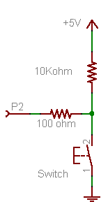
going to use 2 10k resistors I question these things when I have never wired the input side

Simple wiring question
Started by perkunas, Oct 05 2012 12:03 PM
5 replies to this topic
#2

perkunas
-
- Members
-

- 108 posts
Advanced Member
Posted 05 October 2012 - 12:34 PM
oh ya guess I wire it like this too
#3
Nevyn
-

- Members
-
- 1072 posts
Advanced Member
- LocationNorth Yorkshire, UK
Posted 05 October 2012 - 01:07 PM
The pins are multi-functional. So the code you have uses them as digital pins (in this case input). You could connect them to a TTL serial device and use them as a COM port using the SerialPort class. Just remember that you cannot do both at the same time.Wouldn't the pin 0 and 1 that's the TX RX that doesn't seem right for a simple switch?.
I can wire them in but will it work
Regards,
Mark
To be or not to be = 0xFF
Blogging about Netduino, .NET, STM8S and STM32 and generally waffling on about life
Follow @nevynuk on Twitter
#4
carb
-

- Members
-
- 352 posts
Advanced Member
- LocationCrystal River, Florida
Posted 05 October 2012 - 03:37 PM
Perkunas,oh ya guess I wire it like this too
Unless I am missing something you do not need a pullup to make the circuit work.
The following code works fine with a Netduino Classic:
using System;
using System.Threading;
using Microsoft.SPOT;
using Microsoft.SPOT.Hardware;
using SecretLabs.NETMF.Hardware;
using SecretLabs.NETMF.Hardware.Netduino;

namespace NetduinoApplication1
{
  public class Program
  {
    public static void Main()
    {
      InputPort D0input= new InputPort(Pins.GPIO_PIN_D0,false ,Port.ResistorMode.PullUp);
      OutputPort Led = new OutputPort(Pins.ONBOARD_LED, false);
      bool inputstate = false;
      while (true)
      {
        inputstate = D0input.Read();
        Led.Write(inputstate);
        Thread.Sleep(100);
      }
    }
  }
}
The advantages are:
- Less components (no resistors)
- Not applying 5 vdc onto the DIO (they are 5 volt compliant, but normal work at 3.3vdc)
- Uses the resistor.mode.pullup
You can test by placing a jumper wire from ground to D0, which takes it to zero voltage i.e. false. This turns the onboard LED off, remove the wire the internal pullup brings D0 to 3.3vdc i.e. true, onboard LED comes on.
If you want to output to a DIO, change from Onboard_LED to one of the Digital Outputs.
Hope this help,
Chuck
- Paul Newton likes this
#5
perkunas
-
- Members
-
- 108 posts
Advanced Member
Posted 06 October 2012 - 01:41 AM
Thanks I wasn't sure about those on board resistors or how to use them, so I wired it in as the diagram.
Wired in both the same (1st time wiring the input sides)
Next time Ill use the on board resistors.
Its actually coming from a controller so its a relay that closes and not a switch Principals the same.
IDK as long as it works, thanks for the help.
#6
carb
-
- Members
-
- 352 posts
Advanced Member
- LocationCrystal River, Florida
Posted 06 October 2012 - 02:48 AM
No Problem,Thanks I wasn't sure about those on board resistors or how to use them, so I wired it in as the diagram.
Wired in both the same (1st time wiring the input sides)
Next time Ill use the on board resistors.
Its actually coming from a controller so its a relay that closes and not a switch Principals the same.
IDK as long as it works, thanks for the help.
The relay has contacts the same as a switch.
I actual ran the code on a Netduino Classic 4.2 firmware.
There are a lot of code that you can pull snippets from on the forum, I have been mainly using visual basic, but pulled the code snippet from the project pages "pushing the button, action and reaction" project to make sure I had the correct syntax for C#.
Chuck


0 user(s) are reading this topic
0 members, 0 guests, 0 anonymous users


