The Netduino forums have been replaced by new forums at community.wildernesslabs.co.
This site has been preserved for archival purposes only
and the ability to make new accounts or posts has been turned off.
Alongside the new chips, we are also working on firmware for them which lets you expose their pins as virtual IO with simple software settings. Plug one into a breadboard along with a few capacitors and a Komodex GoBus breakout module...and you can easily add IOs and features to your Netduino Go. Or design a module to share with friends. It should be pretty slick.
Seriously?, These chips are useless for prototyping, what kind of breadboard do these fit in???
Seriously?, These chips are useless for prototyping, what kind of breadboard do these fit in???
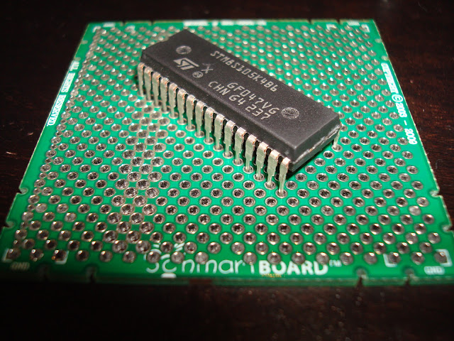
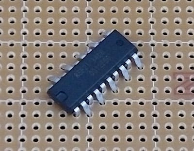
So sorry, I misspoke. You'll need an SDIP->DIP adapter to use these in a traditional 0.1" breadboard. They are SDIP (shrink DIP) chips, so they have a 0.07" pitch.
These chips are an important option for hand-soldered gobus modules, but for prototyping you'll want to use STM8S SMD chips mounted on DIP adapters instead.
If you already bought some of these SDIP chips to use with a breadboard, from one of our international resellers, we can get you a credit for your original purchase price.
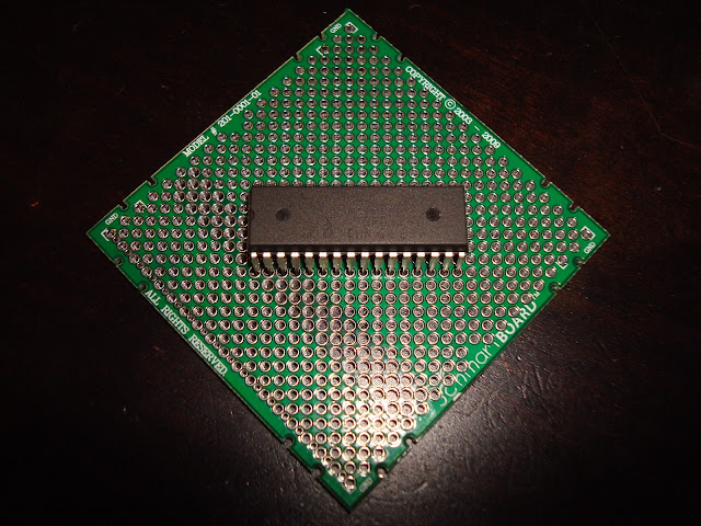
Solution found for the STM8 SDIP chips. These breakout boards from SchmartBoard model # 201-0001-01 for $5 each do the trick. These boards are 0.1" spacing rows, but interleaved at 0.05". Sorry, they look like they are on backorder from the manufacturer, but you can probably find them in stock at your favorite electronics distributor, Fry's Electronics, etc. This board costs more than the chip, but when you've gotta have it now, it works, and is cleaner looking than dead bugging it.
If you use Pythagorean theorem on a right triangle with 0.05" sides, the hypotenuse has a side of 0.07071" which is close enough for our use (targetting 0.07"). From the first pin to the 16th pin, that's only off by about 0.01" total which is smaller than the size of a hole.
ah, nice!
Can it create files for Seedstudio or oshpark? (maybe there are an industriformat for this?)
What I'm also looking for since I was thinking about kicad or eagle are partslibraries or compability, maybe that is not an issue, but I saw that dangerousprototypes etc have created libraries and such.
But DesignSpark looks very nice, need to test that.
Can it create files for Seedstudio or oshpark? (maybe there are an industriformat for this?)
What I'm also looking for since I was thinking about kicad or eagle are partslibraries or compability, maybe that is not an issue, but I saw that dangerousprototypes etc have created libraries and such.
The system outputs Gerber files which the manufacturers can use to produce boards for you.
The program has the ability to import Eagle parts libraries as well. It's not as simple as using a menu option but it's only a five step process. I've done it a couple of times and it works well.
I've tried Eagle and Kicad as well and the thing that puts me off them is that you have to learn how they work. You still have to learn DesignSpark but it is more like a Windows program that the other two. Also, DesignSpark does not have any restrictions on use, unlike Eagle's free version which cannot be used commercially.
If I only could find an sdip32 thingy inside that library now..
Ok, found the part in an STM library here:
http://www.neatinfo.com/designspark/
But, that part turns up purple, lot of anotations on it and so on. hm..
yes, I think I need to find out about that, maybe I can copy an part from the library and put it into the userlibrary for modifications, to create an "socket" instead of an actuall STM8S component.
I also need to find out what is going on the actual pcb, and what is only information in the designer, I guess there are someway to view the pcb in various modes?
I found that it exists zif sockets:
http://www.ebay.com/...t-/350274121433
seems like that one is the same spec, so solder that on, and breakaway headers for the breadboard.
Just need to find out how I can space out things so it fits in the breadboard, but I guess an normal breadboard use 2.54mm pitch, even across the center.
It seems doable now atleast.
The ZIF socket you are referring to has 0.7" pitch on both ends, so it helps with not having to solder the chip down (just the socket), but does not adapt to a standard size.