Netduino home hardware projects downloads community

Jump to content


The Netduino forums have been replaced by new forums at community.wildernesslabs.co. This site has been preserved for archival purposes only and the ability to make new accounts or posts has been turned off.
Photo

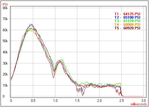
Logging 2.5ms strain curves.


  • Please log in to reply
11 replies to this topic

#1 Spork

Spork

    Advanced Member

  • Members
  • PipPipPip
  • 105 posts

Posted 09 December 2011 - 02:05 AM

Hi all,

I'd like to try to capture events, such as those seen in the graph, from a Vishay 125UN strain gauge.
Posted Image

The time between events is on the order of 15 seconds to a minute, or so. The individual events are (as seen in the graph) on the order of a few milliseconds. I'm not sure how many samples there are in the data that's graphed, but it's probably a few hundred, so let's say that samples will be taken on the order of every 10 microseconds.

My thinking, so far, is that I'll need to build a shield that uses a more-real-time µC to monitor the strain signal, watch for some trigger level, and record something like 1000 samples after the trigger level is reached. Maybe the shield could signal the N+ once the samples have been collected and the N+ would then fetch them and write them to a .dat file on a micro SD.

If I use a 16 bit ADC on the shield, I guess each event would be about 16K. If the helper µC has 16K of RAM and i2c, I guess it could signal the N+ (digital out on the helper connected to digital in on the N+) and the N+ would then pull the sample data via an i2c connection between them? The data xfer from helper to N+ to SD doesn't need to be super fast and I could put an LED on the shield indicating "transfer in progress" so that I know when I can or can't kick off the next event.

Does this sound like a reasonable approach? Are there simpler approaches? Any suggestions as to what would be a good helper µC, keeping in mind that ease of programming and an active user community are more important than cost of the device.

Thanks in advance for any advice!

#2 Magpie

Magpie

    Advanced Member

  • Members
  • PipPipPip
  • 279 posts
  • LocationAustralia (south island)

Posted 09 December 2011 - 09:18 AM

Hi Spork

I think the first thing you need to do is work out your data requirements.

I zoomed in on your graph and I am fairly sure that the graph has only about 240 levels.
I cant see any aliasing.
Therefore probably 256 levels and 8 bit. The Netduino can do better. 10 bit is all I have used.
Similarly the graph also has about 240 samples over the 3 seconds.

If you can I would use 1024 level or 10 bit sampling that is common on the Netduino. Why not.
So to match the quality of that graph or better you could probably use 256 samples at 10 bit resolution.
Therefore you then need 2 bytes per sample and 256 samples. Which is 512 bytes per event.
Just write them into an array as you get them.

Easy.

Then put it onto the SD card after every event has completed.

So you are lucky, your requirements are met by the Netduino alone.
STEFF Shield High Powered Led Driver shield.

#3 Mario Vernari

Mario Vernari

    Advanced Member

  • Members
  • PipPipPip
  • 1768 posts
  • LocationVenezia, Italia

Posted 09 December 2011 - 12:34 PM

@Magpie: I guess the problem is not about the vertical resolution, but rather for collecting several tens of samples within few millisecs. I really can't believe that would be possible, nor ensuring some kind of precise sampling-rate (the MF is managed, and the GC breaks the flow at any time). Another point that Spork should clarify, it *how* the sampling should be triggered. Cheers
Biggest fault of Netduino? It runs by electricity.

#4 Magpie

Magpie

    Advanced Member

  • Members
  • PipPipPip
  • 279 posts
  • LocationAustralia (south island)

Posted 09 December 2011 - 01:27 PM

Thanks Mario. I'll try doing part of the maths again. I looked at the zoomed image and there were about 80 samples per horizontal gridline. So it was 480 samples not 240. Therefore 960 bytes not 512. Time scale in ms not seconds. (Dont know where I got seconds from). Sampling rate is 160/ms = 160,000 samples per second. Albeit for a very short time. So not possible in managed code I guess. Could you do it if you made one long call (3ms) into native code? It says you can get about 500k samples per second at eight bit resolution.
STEFF Shield High Powered Led Driver shield.

#5 Spork

Spork

    Advanced Member

  • Members
  • PipPipPip
  • 105 posts

Posted 09 December 2011 - 04:17 PM

Thanks for the comments. I don't need to match the graph exactly in terms of resolution in either direction. Finer resolution is obviously better but I'll weigh that against simplicity of implementation.

As far as triggering, it seems like it would be similar to a rising trigger on an oscilloscope. In fact, I sometimes think of the project as a "dumbed down" DSO Nano that would have a fixed trigger mode, fixed trigger level, and no screen. Maybe I could actually hack the DSO Nano firmware to save after each trigger, as it also has an micro SD.

I'm completely clueless when it comes to making calls into native code on an N+, but that sounds like it might be an interesting approach for a first version. The native call would need to monitor the strain gauge level indefinitely, watching for a rise up through the trigger level. Once the trigger level is noted, it would sample for something like 3ms, then return. Managed MF code would then shuffle the result to the micro SD. Is MF blocked when native code is running? If so, it wouldn't matter for this application, unless there's something in MF that must run at regular intervals.

What should I read to get up to speed on native code on the N+?

#6 Magpie

Magpie

    Advanced Member

  • Members
  • PipPipPip
  • 279 posts
  • LocationAustralia (south island)

Posted 09 December 2011 - 09:45 PM

Hi Spork As Mario has mentioned the non deterministic nature of the Garbage Collector could pose another problem. If native code could gives you the sample speed required and if you can afford to lose some events it probably isn't such a problem. I'm not sure if you can get around the GC when you are in native code. Maybe by adjusting thread priorities. So it looks like your initial idea could be the simplest, where one processor does the fast A2D and the Netduino does the Webserver, Datalog. You could use the Arduino processor for the A2D ATMega328 as that is probably the next easiest dev environment. Or ... you may be able to drop the Netduino altogether. (cough cough)
STEFF Shield High Powered Led Driver shield.

#7 Stefan W.

Stefan W.

    Advanced Member

  • Members
  • PipPipPip
  • 153 posts

Posted 09 December 2011 - 11:34 PM

The arduino is only able to reach a 9600Hz sampling rate for the adc, so it will not suffice.
I believe that no discovery of fact, however trivial, can be wholly useless to the race, and that no trumpeting of falsehood, however virtuous in intent, can be anything but vicious.
-- H.L. Mencken, "What I Believe"

#8 Spork

Spork

    Advanced Member

  • Members
  • PipPipPip
  • 105 posts

Posted 10 December 2011 - 12:21 AM

The arduino is only able to reach a 9600Hz sampling rate for the adc, so it will not suffice.


Thanks for ruling that out. I think I'll want something on the order of 150kHz to 300kHz sampling rate. The DSO Nano claims to do 1MHz and it's based on a ARM Cortex-M3, so maybe I'll look at something like:

Both of these look fairly friendly.

#9 Stefan W.

Stefan W.

    Advanced Member

  • Members
  • PipPipPip
  • 153 posts

Posted 10 December 2011 - 01:30 PM

Off-topic, but i ended up looking up the specs of the DSO nano, and found http://www.seeedstud...1.html?cPath=77, which has to be the greatest product title ever.
I believe that no discovery of fact, however trivial, can be wholly useless to the race, and that no trumpeting of falsehood, however virtuous in intent, can be anything but vicious.
-- H.L. Mencken, "What I Believe"

#10 Magpie

Magpie

    Advanced Member

  • Members
  • PipPipPip
  • 279 posts
  • LocationAustralia (south island)

Posted 10 December 2011 - 10:29 PM

Off-topic, but i ended up looking up the specs of the DSO nano, and found http://www.seeedstud...1.html?cPath=77, which has to be the greatest product title ever.

That's a nice bit of technology, and it's probably more versatile than "Contemporary Minimalism DSO Nano Stand" suggests.

I was reading the at91sam7x512-au manual and it says that there is a conversion sequencer built into the adc section of the chip and that the adc also has 16kbytes of peripheral memory.

It seems that the sequencer was designed for exactly this purpose, ie fast synchronous adc when you can't guarantee processor availability.

The conversion sequencer allows automatic processing with minimum processor intervention


I am thinking that the adc's 16kbytes of memory is not being used by anything else within the CLR.

So if we have a couple of spare interrupt lines and can write some interop code then we may be able to use this feature.

If anyone can see a reason why this would not work please tell me otherwise I may start looking into this after Christmas sometime.
STEFF Shield High Powered Led Driver shield.

#11 Spork

Spork

    Advanced Member

  • Members
  • PipPipPip
  • 105 posts

Posted 10 December 2011 - 11:14 PM

I was reading the at91sam7x512-au manual and it says that there is a conversion sequencer built into the adc section of the chip and that the adc also has 16kbytes of peripheral memory. It seems that the sequencer was designed for exactly this purpose, ie fast synchronous adc when you can't guarantee processor availability.


Sounds interesting. The 384K samples/sec rate is just about right. It also says that it has "automatic wakeup on trigger and back to sleep mode after conversions of all enabled channels." How would the sequencer get triggered? A little bit of extra electronics that would raise an interrupt signal on an external trigger pin when the signal is above the threshold voltage?

#12 Magpie

Magpie

    Advanced Member

  • Members
  • PipPipPip
  • 279 posts
  • LocationAustralia (south island)

Posted 10 December 2011 - 11:36 PM

I haven't done interop with .net micro before so this may be wrong. Using some C++ code called through interop you would set up the sequencer. The setup would be something like: An external interrupt would trigger the Sequencer to start running. When the sequencer has reached the end of the buffer or a certain number of samples it would then trigger an interrupt that would flow to a handler that can eventually come up through the micro framework. or possibly an interop handler if the .net micro framework doesn't have this. When your managed handler runs it call back down through your interop code to pick up the data, and reset the adc sequencer if neccessary.
STEFF Shield High Powered Led Driver shield.


0 user(s) are reading this topic

0 members, 0 guests, 0 anonymous users

home    hardware    projects    downloads    community    where to buy    contact Copyright © 2016 Wilderness Labs Inc.  |  Legal   |   CC BY-SA
This webpage is licensed under a Creative Commons Attribution-ShareAlike License.