I am trying to create a switch that would toggle power to C328R board (uses 3.3V and max. 60mA according to specs).
So I though I could use an optocoupler.
Here is what I've done:
4n35 input:
netduino pin 7 -> 470 resistor -> 4n35 pin 1.
netduino GND -> 4n35 pin 2
4n35 output:
netduino 3.3V -> 4n35 pin 5
c328r:
TX, RX connected properly
GND -> netduino GND
3.3V -> 4n35 pin 4
Basically I control the optocoupler through digital pin 7 and power of the camera goes through the other side of the optocoupler.
Now for the problem. If the camera isn't attached I get 3.3V on the 4n35 output which is good. But when the camera is attached it reads only about 1V and camera doesn't seem to work (no wonders as it needs 3.3V).
Any idea why camera doesn't get proper 3.3V?
I am sure it is something obvious :-)

using 4n35 optocoupler as a switch
Started by Miha Markic, Nov 24 2011 11:03 AM
14 replies to this topic
#1

Miha Markic
-
- Members
-

- 74 posts
Advanced Member
- LocationNova Gorica, Slovenia
Posted 24 November 2011 - 11:03 AM
Miha Markic, Microsoft MVP C#
Righthand .net consulting and software development
http://blog.rthand.com/
#2
Mario Vernari
-

- Members
-
- 1768 posts
Advanced Member
- LocationVenezia, Italia
Posted 24 November 2011 - 01:14 PM
Hello Miha.
You are close to the right pattern, but still not enough!
The Netduino side is correct: I guess you can choose a lower value for the resistor.
NOTE: it's nice the opto-coupler idea, but you're not obliged to use it. In the following, I'll consider the opto anyway.
Let's go to the output side...
First off, when you connect the collector to a reference voltage (i.e. the supply or the ground), you are basically creating the "common-collector" pattern. It fits perfectly when you need to amplify the current (respect to the base flowing into), but you'll have a voltage attenuation as well.
In other words, there's no way to have a voltage greater than Vbase-0.7V. Since the base is floating, you may take in account the Vcoll (=+3.3V), thus on the emitter the voltage will be always below 2.6V approx.
NOTE: for a photo-transistor the formulas are more complicated than the ordinary way, because they involves photons, and other annoying stuffs.
Secondly, you should add another transistor: PNP this time. For instance, you may use 2N2904, BC307, BC327, etc.
I'd say PNP, because I *really* don't like cutting off the ground from a circuit. I do like connecting all the grounds together (wherever possible), then switching the supply (hot).
4N35: emitter to ground, and collector through a resistor (e.g. 5K-20K) to the PNP base.
Also connect another resistor (5K-20K) from the +3.3V to the 4N35 collector.
Finally, connect the PNP emitter to the +3.3V, and the PNP emitter to the target device.
As you may notice, both the 4n35 and the PNP have their *emitters* hold to a well defined voltage (ground for 4n35, and +3.3 for the PNP). This pattern calls "common-emitter": it amplifies both current and volatge, but inverts the phase. Since you have two pattern in cascade, the phase is reverted on the output...
Hope it helps.
Cheers
Biggest fault of Netduino? It runs by electricity.
#3
Miha Markic
-
- Members
-
- 74 posts
Advanced Member
- LocationNova Gorica, Slovenia
Posted 24 November 2011 - 02:05 PM
Hi Mario,
Thanks for the extensive reply, very helpful. Actually it looks like I don't even need an optocoupler after all.
I thought it'd do for a simple low current switch. Well, nothing is obvious in electronics :-)
Thus I've ripped off from an old circuit board a NPN 8050 transistor. From the datashet it looks like it should work.
Now, here is my new layout.
Netduino pin 7 through 470 resistor to base.
Netduino 3.3V to emiter
8050 collector to C328R.
If I omit C328R (for testing) and measure the voltage between collector and GND I get ~5.5V (on) and ~3.6V (off). I'd expect something like 3.3V and 0V.
Any idea where does 5.5V come from? I'd test with camera but with these voltages I am cautios
Miha Markic, Microsoft MVP C#
Righthand .net consulting and software development
http://blog.rthand.com/
#4
Mario Vernari
-
- Members
-
- 1768 posts
Advanced Member
- LocationVenezia, Italia
Posted 24 November 2011 - 02:44 PM
Nope!
Even without opto, you need two transistors (NPN+PNP). Using the opto, just the PNP.
Take a look at the NPN symbol: the arrow is directed outgoing the emitter. The arrow indicates the current flow, thus you can't connect the emitter of a NPN to a positive source: it won't work.
You must follow the above instructions.
If you don't like the transistors, you may solve your problem with a trick, unless the camera requires many current.
You can pick a 74HC04: it's a 6-NOT gates. Drive *ONE* NOT using the Netduino port, then connect all the remaining 5 NOTs in parallel, as cascade of the first one.
Supply your camera with the super-NOT...
Cheers
Biggest fault of Netduino? It runs by electricity.
#5
Miha Markic
-
- Members
-
- 74 posts
Advanced Member
- LocationNova Gorica, Slovenia
Posted 24 November 2011 - 03:38 PM
Nope!
Even without opto, you need two transistors (NPN+PNP). Using the opto, just the PNP.
OK. I'll go with an opto + PNP.
Take a look at the NPN symbol: the arrow is directed outgoing the emitter. The arrow indicates the current flow, thus you can't connect the emitter of a NPN to a positive source: it won't work.
You must follow the above instructions.
Right, my bad. Can't I just switch the pin where camera is attached to? I mean can't I use NPN and connect camera to the emitter and voltage to the collector?
In other words, aren't NPN and PNP the same, taken granted that you switch C and E?
If you don't like the transistors, you may solve your problem with a trick, unless the camera requires many current.
You can pick a 74HC04: it's a 6-NOT gates. Drive *ONE* NOT using the Netduino port, then connect all the remaining 5 NOTs in parallel, as cascade of the first one.
Supply your camera with the super-NOT...
LOL. I'll take the easiest route I guess.
I made a Fritzing sketch based on your suggestion. Two questions:
- is it correct? (white is Pin 7, black is GND and red is 3.3V)
- can I use NPN instead of PNP and just switch C and E?
Attached Files
-
 switch.png 129.16KB
52 downloads
switch.png 129.16KB
52 downloads
Miha Markic, Microsoft MVP C#
Righthand .net consulting and software development
http://blog.rthand.com/
#6
Miha Markic
-
- Members
-
- 74 posts
Advanced Member
- LocationNova Gorica, Slovenia
Posted 24 November 2011 - 03:48 PM
Nope!
Even without opto, you need two transistors (NPN+PNP). Using the opto, just the PNP.
Can you clarify one more thing for me. As I browsed around I mostly see using one transistor for the switch functionality,
i.e.
Sample switch
Cheers
Miha Markic, Microsoft MVP C#
Righthand .net consulting and software development
http://blog.rthand.com/
#7
Mario Vernari
-
- Members
-
- 1768 posts
Advanced Member
- LocationVenezia, Italia
Posted 24 November 2011 - 04:11 PM
The Fritzing is almost correct, but you must swap C and E.
Good point the article: there are many useful images. This one for example...
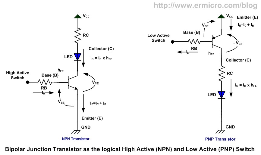
The Netduino output will drive the "High Active Switch" pin.
Now, image the PNP (right) base ("Low Active Switch" pin) to the NPN (left) collector lead.
Also, substitute the left-side LED+RC, with your camera.
Finally, we agree on Vcc=+3.3V.
Oh, well...
=== Netduino out: OFF ===
there's no voltage, thus no current flowing through the NPN base. The NPN is off, thus no current flowing through its C-E leads. Since you have a opto-transistor, the missing light on the led stops any C-E current, as stated.
Now, have a look at the PNP E-B route: why the hell the current should flow from the PNP E (+3.3V), through the B, then RB, then RC? It's much like a water pipe: no fall, no flow...
Thus, the PNP is also off, and no current are flowing through the E-C route of the PNP.
Your camera is unpowered.
=== Netduino out: ON ===
There's voltage across the NPN RB route, thus current through B-E. That current will be enough to "close" the NPN, thus C-E are almost the same point (0.1-0.2V).
This time, the current may flow from the PNP E, thru B, thru RB, thru the closed NPN.
The PNP is also closed, and similarly the E-C leads are nearly the same point.
On the PNP C lead there's a voltage very close to 3.3V, thus...
...your camera is powered!
Hope now it's cleared!
Cheers
Good point the article: there are many useful images. This one for example...
The Netduino output will drive the "High Active Switch" pin.
Now, image the PNP (right) base ("Low Active Switch" pin) to the NPN (left) collector lead.
Also, substitute the left-side LED+RC, with your camera.
Finally, we agree on Vcc=+3.3V.
Oh, well...
=== Netduino out: OFF ===
there's no voltage, thus no current flowing through the NPN base. The NPN is off, thus no current flowing through its C-E leads. Since you have a opto-transistor, the missing light on the led stops any C-E current, as stated.
Now, have a look at the PNP E-B route: why the hell the current should flow from the PNP E (+3.3V), through the B, then RB, then RC? It's much like a water pipe: no fall, no flow...
Thus, the PNP is also off, and no current are flowing through the E-C route of the PNP.
Your camera is unpowered.
=== Netduino out: ON ===
There's voltage across the NPN RB route, thus current through B-E. That current will be enough to "close" the NPN, thus C-E are almost the same point (0.1-0.2V).
This time, the current may flow from the PNP E, thru B, thru RB, thru the closed NPN.
The PNP is also closed, and similarly the E-C leads are nearly the same point.
On the PNP C lead there's a voltage very close to 3.3V, thus...
...your camera is powered!
Hope now it's cleared!
Cheers
Biggest fault of Netduino? It runs by electricity.
#8
Miha Markic
-
- Members
-
- 74 posts
Advanced Member
- LocationNova Gorica, Slovenia
Posted 24 November 2011 - 09:38 PM
Also, substitute the left-side LED+RC, with your camera.
You mean on the right, since I am attaching camera to PNP's collector?
Miha Markic, Microsoft MVP C#
Righthand .net consulting and software development
http://blog.rthand.com/
#9
Mario Vernari
-
- Members
-
- 1768 posts
Advanced Member
- LocationVenezia, Italia
Posted 25 November 2011 - 04:36 AM
Yes.You mean on the right, since I am attaching camera to PNP's collector?
Anyway, you should test how much current your camera requires. Probably won't be an issue, but maybe the resistor value should be adjusted.
Cheers
Biggest fault of Netduino? It runs by electricity.
#10
Miha Markic
-
- Members
-
- 74 posts
Advanced Member
- LocationNova Gorica, Slovenia
Posted 25 November 2011 - 07:35 AM
Yes.
Anyway, you should test how much current your camera requires. Probably won't be an issue, but maybe the resistor value should be adjusted.
Cheers
Camera specs say it requires 60mA. I guess that shouldn't be a problem.
If I understand correctly dual transistor scheme is required to avoid the voltage drop when a single transistor is used?
Miha Markic, Microsoft MVP C#
Righthand .net consulting and software development
http://blog.rthand.com/
#11
Mario Vernari
-
- Members
-
- 1768 posts
Advanced Member
- LocationVenezia, Italia
Posted 25 November 2011 - 08:13 AM
Okay, about the current.Camera specs say it requires 60mA. I guess that shouldn't be a problem.
If I understand correctly dual transistor scheme is required to avoid the voltage drop when a single transistor is used?
Let's suppose the (PNP) transistor's current gain (called "hFE") at least 100. It means we must flow through its base (via E) a current *greater* than:
Ib > Ic / hFE = 60mA / 100 = 600uA
Now, when the NPN is closed, the PNP base current is flowing from Vcc (PNP E), thru PNP B, thru RB, thru NPN (being much like a short).
So, you have a small voltage drop on PNP E-B (about 0.7V), but all the remaining voltage is across RB...
Also:
RB = (Vcc-Veb) / Ib = (3.3-0.7) / 600u = 4.3K
Thus, the PNP RB resistor must be *less than* 4.3K.
As you may see, the suggestion at-first-glance I gave you yesterday was partially incorrect. However, the above calculation is pessimistic, thus you may use a normal 4.7K resistor.
Two stages...
Your primary goal is to amplify the current, without reversing the polarity of the output, that is when the Netduino output goes low, your appliance should be unpowered. Vice versa, when the output goes high, the camera should be 3.3V powered.
The "common-emitter" pattern amplifies the available current, without any voltage attenuation. BTW, it amplifies the voltage as well. The counterpart of this circuit is that acts like a NOT-gate, thus you must use a couple of these stages to revert the polarity.
Anyway, the double stage is not just because the polarity.
You can't power your camera through a resistor, because it would drop the voltage, proportionally to the current flowing thru. The "well-done" switch is on the "hot" supply (+), as shown here for instance.
You may *avoid* the first (NPN) stage (in your case the 4n35), when ALL the followings match:
- you accept to drive your appliance using a negative logic (NOT'ed);
- the Vcc (PNP emitter) is tied at the same supply of your driving logic (i.e. Netduino port);
- the PNP current amplification is enough (see above).
Cheers
Biggest fault of Netduino? It runs by electricity.
#12
Miha Markic
-
- Members
-
- 74 posts
Advanced Member
- LocationNova Gorica, Slovenia
Posted 25 November 2011 - 08:58 AM
You may *avoid* the first (NPN) stage (in your case the 4n35), when ALL the followings match:
1. you accept to drive your appliance using a negative logic (NOT'ed);
2. ]the Vcc (PNP emitter) is tied at the same supply of your driving logic (i.e. Netduino port);
3. the PNP current amplification is enough (see above).
First, let me tell you, that your help (and patience
 ) is greatly appreciated.
1. I don't care that much. NOT is fine by me if it makes things easier.
2. I am using a 3.3V pin from Netduino to power the camera. I assume this is OK.
3. Pin 7 is capable (per specs) of 16mA. Camera is supposed to use max 60mA. 8550 Hfe min is 85, that makes plenty of current, correct?
I guess I don't even need that additional resistor from Vcc to Pin 7 (the one that makes sure that there is no current flowing when off).
4. I've calculated Rb as (3.3V - 0.92) / (60mA / 85) = 3.371K. AFAIK it can be a lower value, thus 1K will still work (but perhaps use more current than required). Or it can be a slightly value, because the calculation is worst case scenario. So, the higher the value less current is used but there is no problem if more current is used (apart from draining the battery sooner).
So, I've attached another sketch, this time using a single PNP. Rb is put as 4.7K but I can use 1K just fine.
Attached Files
-
switch.png 2.89KB
34 downloads
Miha Markic, Microsoft MVP C#
Righthand .net consulting and software development
http://blog.rthand.com/
#13
Miha Markic
-
- Members
-
- 74 posts
Advanced Member
- LocationNova Gorica, Slovenia
Posted 25 November 2011 - 09:24 AM
Note that I've actually tested the latest design and it works.
Thanks for all the help and if you have any comment I'd be glad to hear it.
Cheers,
Miha
Miha Markic, Microsoft MVP C#
Righthand .net consulting and software development
http://blog.rthand.com/
#14
Mario Vernari
-
- Members
-
- 1768 posts
Advanced Member
- LocationVenezia, Italia
Posted 25 November 2011 - 12:32 PM
Happy to help you, and anyone bumped to a similar task. I guess should be very common.
You are also correct about keeping the resistor lower than 4.7K, because the hFE is lower than the supposed 100. A resistor of 1K is surely a good value, well tolerated of any Netduino output. Thus, you may reserve the high-current outs for something useful!
Cheers
Biggest fault of Netduino? It runs by electricity.
#15
Miha Markic
-
- Members
-
- 74 posts
Advanced Member
- LocationNova Gorica, Slovenia
Posted 25 November 2011 - 01:13 PM
Let me just add that whoever created an autosynchronizing-speed UART on C328R should be sent to jail.  I need this switch to reset the camera several times before it gets synchronized. And even then it fails out of sync after approx. 15s. Blah.
I need this switch to reset the camera several times before it gets synchronized. And even then it fails out of sync after approx. 15s. Blah.
Miha Markic, Microsoft MVP C#
Righthand .net consulting and software development
http://blog.rthand.com/


1 user(s) are reading this topic
0 members, 1 guests, 0 anonymous users


