The Netduino forums have been replaced by new forums at community.wildernesslabs.co.
This site has been preserved for archival purposes only
and the ability to make new accounts or posts has been turned off.
Oh, okay... So it looks like things are working but the trouble is changing the program on the BlinkMs...
With a name like Spike, I don't think you're afraid of anything
One big question: it looks like you're using I2C to program/control the BlinkM's. I2C is on analog pins 4 and 5. Do you have the data lines plugged into A4/A5--or A0/A1?
Also, do BlinkMs have their own pull-up resistors built-in or do you need to add those?
Chris
Ah that may well be the problem, I have it connected in A0 and A1. Sorry I am very new to all these electrical phrases and acronyms, maybe a 101 guide and or glossary would be a good idea!
I don't know about the pull-up resistors, neither do I really understand what they are!
Thanks very much for your help, I will try switching the lines over...
We are all new to electronics at some point...no worries at all.
Here's a link to our tech specs page. In the right column, all the peipheral features are listed along with which pins they use. It's a good reference to keep handy.
http://www.netduino....duino/specs.htm
Please let us know how switching the lines works for you...
Chris
Do you have the two I2C wires swapped by any chance? They have to go in the right way (one is the "clock"; the other is "data").
Also, you'll want to look at the BlinkM specs regarding pull-up resistors. Basically, I2C works by making the default voltage 3.3V/5V (binary 1) and then it pulls "down" the voltage by connecting the data line to ground (0V = binary 0). It does this for both the clock and the data line. This enables a bunch of devices to use the same line--pretty clever.
To pull up the line to a default voltage, it needs a specific value of resistors--different based on the number of devices, line voltage, etc. Since you're working with BlinkMs _only_, they should give you a set of resistor values to use.
Chris
P.S. stacyh3 mentioned that he needed to add proper pull-up resistors (see post #2 in the thread). Perhaps you could PM him and see if he would post the ohm values of the resistors he used?
I have the cables in the correct analog pins. I found this in the documentation:
1.2.2.
MinM Digital Inputs
The ‘d’ and ‘c’ lines (I2C data and clock) can also function as digital inputs. This allows MinMs
to alter light script playback like MaxM. Normally these lines are HIGH, but can be pulled
LOW through a 220 ohm resistor. In the input commands (‘i’ - “Input Read and Jump” and ‘I’ -
“Input Jump Immediate”), these inputs are numbered 0x40 (‘d’) and 0x41 (‘c’).
So do I need to buy a resistor or 2?
Looking at the BlinkM datasheet, it appears that the I2C (SDA/SCL) lines need 4.7K pull-up resistors (i.e. tied to the same header that provides power to the BlinkM).
Try 3.3V power/pull-ups first. If that doesn't work, try 5V power/pull-ups.
We'll also get some in here to play with...
Chris
I am going to uni this week so I wont have opportunity to get the bits for a while I am afraid, I am not sure on what the circuitry would look like completed either!
I have just about settled into university now, so hopefully I can get this to work. Do I need to get one of these (http://www.maplin.co...x?ModuleNo=2163) and find the correct type of resistor from the pack? or am I looking for the wrong thing?
I have just about settled into university now, so hopefully I can get this to work. Do I need to get one of these (http://www.maplin.co...x?ModuleNo=2163) and find the correct type of resistor from the pack? or am I looking for the wrong thing?
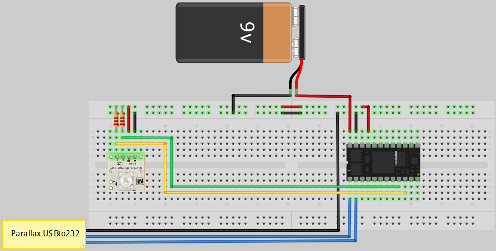
Ok well I went and got some 4.7k, 3.3k, and 5k resistors and added them to the circuit as below, still had no luck, I don't see what I am doing wrong. Any help is appreciated.
Ok well I went and got some 4.7k, 3.3k, and 5k resistors and added them to the circuit as below, still had no luck, I don't see what I am doing wrong. Any help is appreciated.
Hi Spike,
The I2C data lines should be connected from the Netduino to the I2C device's I2C inputs directly.
The two pull-up resistors should go from the two I2C data lines to 3.3V (or 5V) power--pick your voltage based on the requirements of the device. In this case, probably 5V.
Do this:
1. Move one side of the 2 I2C resistors to the 3.3V power line on the breadboard.
2. Move the two I2C data line jumper wires to the left so they are directly connected to the device.
3. If that doesn't work, add a 5V line to the breadboard and connect the 2 resistors there instead.
Someone who is skilled in Fritzing may be able to post a schematic for you here
Chris
Ah! Ill try and work out what that has actually done, but it now works, the LED now stops on green! Thanks very much for your help! Now I just need to work out how to program it
I have attached a photo so you can see what it looks like, I am using 4.7k resistors.
Ok well I went and got some 4.7k, 3.3k, and 5k resistors and added them to the circuit as below.
The resistors must be connected between I2C signal lines and supply voltage, so one goes from 'c' to '+' and the second from 'd' to '+'. I hope the attached image is understandable enough (I have put both resistors into same '+' hole on the picture, you can bend the leads so they fit better into a different hole).
Edit: Deleted the image because there has been much better one posted meanwhile.
Ok I am making some progress with this now. I am trying to get the BlinkMinM LED to execute commands based on the value sent from my PC via serial connection. I have used the serial communication code as found here.
I am stumped as how to read data back from a transaction with the BlinkMinM as I cant see that anything other then the number of bytes read is returned from I2CDevice.I2CReadTransaction. I am hoping to work out the duration of a predefined "light script" in order to allow a series of scripts to be run one after the other without truncating the ends of them.
How do I get data back from the LED? I have read through this thread but don't understand how the data is returned from the read transaction. To get the duration of a script I need to run the c# equivalent of this
// read line 3 of script id 0
{‘R’,0,3} // read line 3
on each line in the script (max 50 lines).
Here is some of my WIP code.
static void blinkmCommand(I2CDevice I2CDeviceObject, char commandString, byte r = 0x00, byte g = 0x00, byte b = 0x00)
        {

            I2CDevice.I2CTransaction[] DoSomething = new I2CDevice.I2CTransaction[5]
            {
                I2CDevice.CreateWriteTransaction(new byte[] {(byte)'o'}),
                I2CDevice.CreateWriteTransaction(new byte[] {(byte)commandString}),
                I2CDevice.CreateWriteTransaction(new byte[] { r }),
                I2CDevice.CreateWriteTransaction(new byte[] { g }),
                I2CDevice.CreateWriteTransaction(new byte[] { b })
            };

            I2CDeviceObject.Execute(DoSomething, 1000);
            Thread.Sleep(scriptLengthFinder(I2CDeviceObject, (byte)commandString));
        }

        private static int scriptLengthFinder(I2CDevice I2CDeviceObject, byte scriptID)
        {
            int scriptlength = 0;

            for (int i = 0; i < 49; i++)
            {

                I2CDevice.I2CReadTransaction[] findLen = new I2CDevice.I2CReadTransaction[3]
                {
                    I2CDevice.CreateReadTransaction(new byte[] {(byte)'r'}),
                    I2CDevice.CreateReadTransaction(new byte[] {scriptID}),
                    I2CDevice.CreateReadTransaction(new byte[] {(byte)i})
                };

                //This is where I am stuck...
                byte[] response = (byte)I2CDeviceObject.Execute(findLen, 1000);
            }
            return scriptlength;
        }
Hi Spike,
I know it's been a while since your last post, but have you made any progress on this? Or has anyone else managed reading from the BlinkM or other I2C device?
I'm having the same problem. I can do what I like writing to the BlinkM but my netduino crashes when I try to do any reads.
Cheers
Raymond
I think it has something to do with the repeated start bit problem as mentioned by some other people on the forum regarding I2C devices. Well thats the only conclusion I have come to.
Anyone here used BlinkMs with their Netduino yet? Any tips for trustme?
If not, we should probably get some in here to play with as well.
Chris
Sorry, I had not seen this request before. Anyway, I used my BlinkM fine with Netduino Mini. The source code is attached. There is a small driver that I have started to build, that supports just two commands gotoColor and fadeColor, that were sufficient for my initial testing, but with this framework you can add all the commands you need. After all this time, maybe both Spike and TrustMe now have projects more advanced than mine. Anyhow, in the case this could help in any way.