Astable NE555 Calcuator and Data Logger
#1
Posted 05 March 2011 - 01:40 PM
This project has two components, an extension to the simple web server I have previously posted on the project showcase and a Silverlight applicaiton to interact with the user.
The simple web server has been modified to allow the user to send configuration information to the Netduino Plus. It can also act as a simple data logger. This obviously has some restrictions such as the maximum sample rate etc. but is effective enough for my needs at this time.
Interaction with the user is facilitated by a Silverlight application. This has three components each represented by a seperate tab on the interface.
The parameters tab allows the user to enter the parameters for the calculations. The user enters three of the four parameters from R1, R2, C1 and F and the application will calcuate the remaining parameter
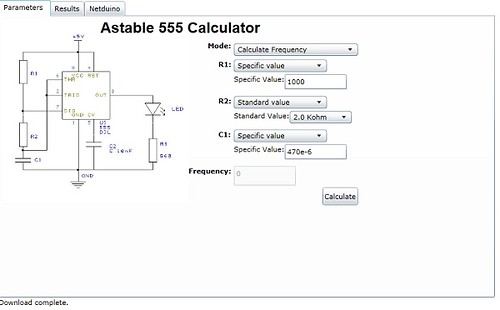
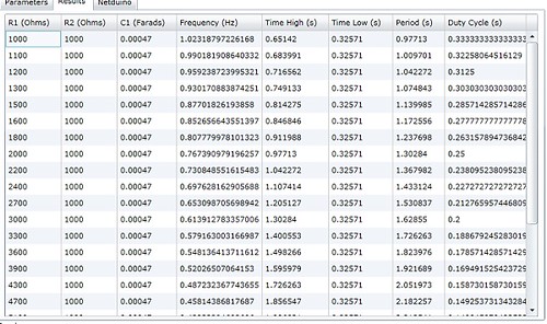
When calculating F, the system also allows the user to select a range of values for R1, R2 and C1 producing a table of results. The second tab shows the results of the calculation:
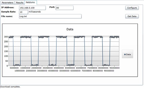
The third tab allows the user to communicate with the Netduino and presents data which has been captured by the board on A0.
If you are interested, the full source code can be found on my blog entry about this project.
Regards,
Mark
15 March 2011 - Replaced links to images with Flickr links.
To be or not to be = 0xFF
Blogging about Netduino, .NET, STM8S and STM32 and generally waffling on about life
Follow @nevynuk on Twitter
#2
Posted 05 March 2011 - 06:33 PM
#3
Posted 06 March 2011 - 06:28 AM
The concept was to build an application which would perform the calculations for me and then allow me to compare the theory to the implementation.Firstly, I've made some effort to understand the sense of the project, because it's a double-function application. In the sense, you made a 555 calculator and an oscilloscope, but this could be used for any kind of signal as long it's bounded in the ADC range.
If memory serves, the minimum supply voltage for the 555 is 4.5V (I was using 5) and this generates an output equal to the supply so I was already outside the range for the analog input to the Netduino. To get over this I fed the output through a voltage divider. If you look at the range of the values on the chart at the end of the pot you will see that the maximum is under 300 whereas the range for the ADC is 1023.I'd specify also some info about the connection of the 555 output to the Netduino ADC. If you're going to power the oscillator with 12V, you may damage the ADC input.
I like the idea of the dynamic generation of the results and wave form. The application already allows the user to select a range of values and see the results. The image below shows the results when R1 is set to a range:
Going forward, I think the first step is to make the application more robust and get some better error trapping in the system - maybe some validation.
Regards,
Mark
15 March 2011 - Replaced links to images with Flickr links.
Edited by Nevyn, 15 March 2011 - 07:46 AM.
To be or not to be = 0xFF
Blogging about Netduino, .NET, STM8S and STM32 and generally waffling on about life
Follow @nevynuk on Twitter
#4
Posted 06 March 2011 - 03:37 PM
0 user(s) are reading this topic
0 members, 0 guests, 0 anonymous users