Netduino home hardware projects downloads community

Jump to content


The Netduino forums have been replaced by new forums at community.wildernesslabs.co. This site has been preserved for archival purposes only and the ability to make new accounts or posts has been turned off.
Photo

Begginer help: Using PWM


  • Please log in to reply
4 replies to this topic

#1 capn

capn

    Member

  • Members
  • PipPip
  • 14 posts
  • LocationNC

Posted 14 February 2011 - 04:34 PM

Hey Everyone!

In my goal to get my robot controller up and running, I want to know more about the use of PWM on the Netduino.

My question for today is, How do you setup and use the Netduino PWM pins?

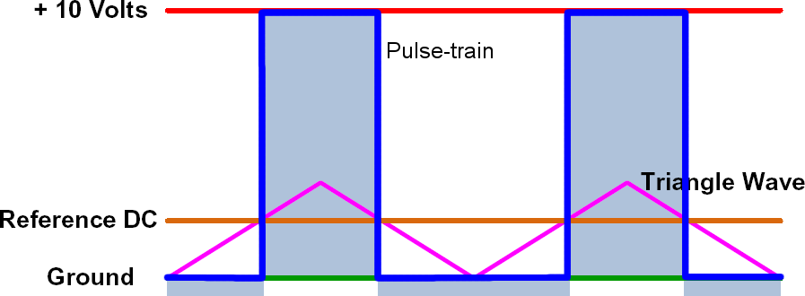
I'll give just a brief explanation of how Pulse Width Modulation (PWM) is done from a hardware standpoint, for non-hardware people. Usually there is a triangle wave (most commonly from a 555) that is then compared with a reference voltage (using a comparator). Comparing the reference voltage (orange) with the triangle wave (magenta), you get a square wave out (blue). The width of this square wave compared to the TOTAL width (leading edge to leading edge) between the two square waves is called the "duty cycle", which can be from 0-100%.

Posted Image

So from the hardware you have some variables that you have control over, such as:
  • Frequency of the triangle wave
  • Reference voltage (this becomes comparing bits)
  • Duty cycle

These are some very important parameters to control when making a circuit. So how do I configure these parameters on the Netduino?

Can you more experienced guys help me fill in my code?

public static void Main()
{
AnalogInput xAxisInput = new AnalogInput(Pins.GPIO_PIN_A1);     //reading an analog input this will by my "VRef" as it were
int xAxisValue= xAxisInput.Read();                              //int for that analog input


//How is the PWM properly setup here??

PWM.frequency(150Hz);   //setting the frequency of of my "triangle wave" How is this done???
int PwmDutyCycle;       //value for my PWM duty cycle


//I have made the range for directions 0-1023, with a 128bit "dead zone"

if (xAxisValue > 576)
{
    PwmDutyCycle = xAxisValue/1023      //setting my duty cycle 50-100%.  Is this right???
    Direction1.Write(PwmDutyCycle);     //gives the motor 1, direction 1 a true reading, this is forward with speed
}
else if(xAxisValue < 448)
{
    PwmDutyCycle = (1023-xAxisValue)/1023      //setting my duty cycle 50-100%.  Is this right???
    Direction2.Write(PwmDutyCycle);            //gives the motor 1 direction 2 a true reading, this is reverse with speed
}

Be patient with me, I'm new to this.


#2 CW2

CW2

    Advanced Member

  • Members
  • PipPipPip
  • 1592 posts
  • LocationCzech Republic

Posted 14 February 2011 - 04:59 PM

My question for today is, How do you setup and use the Netduino PWM pins?

Instantiate a PWM object and call its SetDutyCycle() method:

// There are 4 PWM channels available on pins D5, D6, D9, D10
pwm = new PWM(Pins.GPIO_PIN_D5);
pwm.SetDutyCycle(50);
Note: The current .NET Micro Framework implementation supports only 'Fast-PWM' (left-aligned), so if you need center-aligned PWM displayed in your picture, it would require modification in firmware.

#3 Philip

Philip

    Member

  • Members
  • PipPip
  • 26 posts
  • LocationPreston, England

Posted 28 February 2011 - 06:37 PM

Hi All, I've been using PWM.SetDutyCycle() to control a pair of motors. Being of 'advanced' years (not too advanced!) I was oblivious to the 10 kHz audio this was generating until one of my students pointed it out to me. I *think* I am right in saying that the default frequency is 10 kHz for the PWM. My question is this - can we have a way of changing this default frequency to something outside the audio range? (or even below the audio range). I appreciate that SetPulse(Period, Duration) could do it, but in a not very convenient way. Could the SetDutyCycle() method have a second parameter of Frequency? Phil

#4 acetate

acetate

    Member

  • Members
  • PipPip
  • 26 posts
  • LocationSeattle, WA

Posted 28 February 2011 - 08:08 PM

Phillip,
Setting the PWM clock is on the wish list for 4.1.2 firmware. You can use setpulse to control the period and duration. It is one more line of code. You can see my example at the end of this thread. You can also search around for some more clearer examples. This blog post is the one that helped me the most.

#5 Chris Walker

Chris Walker

    Secret Labs Staff

  • Moderators
  • 7767 posts
  • LocationNew York, NY

Posted 07 March 2011 - 11:14 AM

Phillip,
Setting the PWM clock is on the wish list for 4.1.2 firmware. You can use setpulse to control the period and duration. It is one more line of code. You can see my example at the end of this thread. You can also search around for some more clearer examples. This blog post is the one that helped me the most.


I can confirm that the new PWM features will be making it into the v4.1.2 beta firmware, including setting a custom frequency.

Chris


0 user(s) are reading this topic

0 members, 0 guests, 0 anonymous users

home    hardware    projects    downloads    community    where to buy    contact Copyright © 2016 Wilderness Labs Inc.  |  Legal   |   CC BY-SA
This webpage is licensed under a Creative Commons Attribution-ShareAlike License.