The Netduino forums have been replaced by new forums at community.wildernesslabs.co.
This site has been preserved for archival purposes only
and the ability to make new accounts or posts has been turned off.
Getting started with Netduino Mini (early instructions)
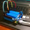
Hello! I just found the time to confirm that my new (well new to here) Netduino Mini works. After mounting it on a breadboard and connecting it accordingly to a USB device, I borrowed the MiniUSB one that's for the Arduino Mini. I then wired it accordingly: Power on the USB device was connected to the +5 and ground positions. The TX and RX on the USB end went to the Netduino, and then made sure that Putty saw it, with regards to the settings. And hit the ESC key. I then got this blurb:
Netduino Mini
1. TTL UART (COM1) 2. RS232 UART (COM2)
Which transport (1 or 2)? 1
Switching transport to TTL UART (COM1)... .NetMF v4.1.2821.0 NetduinoMini, Build Date: Feb 14 2011 00:59:53 ARM Compiler version 400902
TinyCLR (Build 4.1.2821.0)
Starting... Created EE. Started Hardware. t?ÔÊMSdbgV1qt?ÔÊMSdbgV1wKft?ÔÊMSdbgV1eâ¦t?ÔÊMSdbgV1cPt?ÔÊMSdbgV1i$Kt?ÔÊMSdbgV1oǽt?ÔÊMSdbgV1MvÊ8t?ÊMSdbgV1K<?t?ÔÐÊMSdbgV1A°'7t?ÔÐ ÊMSdbgV1GSÑ0t?ÔÐ ÊMSdbgV1Uú't?ÔÐ ÊMSdbgV1Y<ü(t?ÔÊMSdbgV1_ß /t?ÔÊMSdbgV1^xt?ÔÊMSdbgV1t?ÔÊMSdbgV1þwt?ÔÊMSdbgV1pt?ÔÊMSdbgV1ÒÈgt?ÔÊNo debugger! Create TS. Loading start at 134134, end 1462d4 Attaching file. Assembly: mscorlib (4.1.2821.0) (3880 RAM - 33236 ROM - 19134 METADATA)
Hello!
Thank you Chris. Your instructions on how to change a Netduino program such as blinky from running on the basic device to the mini simply by changing one referenced hardware library were right on the money. Although the properties tab also needs to be checked to make sure its set accordingly to accommodate a proper delivery of code otherwise an error will be flagged. It wanted me to check the hardware. I did and then checked the properties tab. Then it worked and I'm running.
I did this for the program code:
            // write your code here
            OutputPort led = new OutputPort(Pins.GPIO_PIN_20 , false);
Inside the braces of course. I randomly chose that pin, and I was off.....
Now to work on more complicated ones. Presumably the TW lines on the bottom (TWD and TWCK) are for I2C style communications?
Hello! Yes exactly. According to the Atmel supplied data sheet, the pair are indeed considered to be compatible, just need to be programmed accordingly. I figured that once I get an idea of my intended project, I'll be mating a TI I/O device that uses that style of communications to it, probably their PCF8574A part, or the PCF8575 one. It actually depends on what I have in mind..... To be honest it simply depends on what that will be. I've enclosed copies of the data sheets for those two parts. Oh and thank you for your fast answer.
Netduino Mini - Cannot get menu on pressing escape!
Connected Mini to FTDI Basic -> (pin 24 to 9V, pin 23 to gnd, pin 23 to FTDI Gnd, pin 11 to FTDI TX, Pin 12 to FTDI RX) FTDI is on 3.3V
I get all the boot messages on putty all upto the ready message. Thereafter it freezes and does nothing whether I press escape or any other key. So I dont get the menu to change the default port to TTL UART
Any ideas what could be wrong?
Is this a new Netduino Mini? Where did you buy it?
It sounds like the deployment port may already be on the TTL UART...if you're getting the boot messages. Try pinging it from MFDeploy (after disconnecting from your terminal program).
Chris
Did you first try to erase it by applying 5V to the gold ERASE pad? It's located at the top on the right hand side.
Flashing instructions after erasing are here toward the bottom of the page, http://forums.netdui...-v420-update-1/
After several months, trying this again :-). Reset my mini by applying 5v to the gold erase pad, attempted to connect via SAM-BA and it says "no valid processor found".
I am connecting via FTDI breakout USB cable in 3.3V mode:
After several months, trying this again :-). Reset my mini by applying 5v to the gold erase pad, attempted to connect via SAM-BA and it says "no valid processor found".
I am connecting via FTDI breakout USB cable in 3.3V mode:
- ground to pin 23
- 3.3V to pin 21
- RXD from breakout board to pin 11
- TDX from breakout board to pin 12
Any thoughts?
Well yes. When uploading fresh firmware to the little guy, the user needs to connect to the RS232 points at RS232 levels. The FTDI breakout produces TTL: or CMOS compatible output levels. So you'd need USB to RS232 adapter to do that. I normally use one for the Basic Stamp gang to make it work since its within four solar diameters of the specifications in the FTDI datasheet for just such a design. It also expects 5v at the positive voltage connection when working. The TTL management connections are fine for sending it the firmware for TTL stuff although you might need to do the same thing as you just did for the regular fresh firmware for it.
I expect Chris will chime in with appropriate things as soon as he's around.
Most of those eBay adapters use the Prolific chipset, and sadly they aren't reliable. There are histories of people having to spend more time with the adapter then with their projects.
The chipset behind the Keyspan design already a known object. Those two are unknown. I also chose in my explanation the one made by Parallax because its exactly what the designers at FTDI had in mind when designing a USB to Serial (RS232) adapter. The firm (FTDI) also sells an adapter along the same lines, however a DB9 connector will be needed that mates with the chosen adapter.
Thanks guys! Yeah I have one of the Prolific adapters and I spent about an hour messing with the drivers before deciding to give up on it. Keyspan it is then.


 Chris
Chris