Hi,
In my third blog post I'm demonstrating how to connect an alpahnumeric 16x2 LCD display to the Netudino. I created a library based on Arduino LiquidCrystal lib and earlier work done by Pavel Bansky. The LCD can be connected both directly (in 4-bit and 8-bit modes) or via a 74HC595 shift register.
Here is the blog post: http://geekswithblog...id_crystal.aspx
The source code is here: http://cid-4c7ec0c21...l^_20100905.zip

LCD Library
Started by Szymon, Sep 05 2010 06:20 PM
41 replies to this topic
#1

Szymon
-
- Members
-

- 108 posts
Advanced Member
- LocationPoland, Krakow
Posted 05 September 2010 - 06:20 PM
#2
greg
-

- Members
-
- 169 posts
Advanced Member
- LocationChicago, IL
Posted 05 September 2010 - 06:51 PM
Hi,
In my third blog post I'm demonstrating how to connect an alpahnumeric 16x2 LCD display to the Netudino. I created a library based on Arduino LiquidCrystal lib and earlier work done by Pavel Bansky. The LCD can be connected both directly (in 4-bit and 8-bit modes) or via a 74HC595 shift register.
Here is the blog post: http://geekswithblog...id_crystal.aspx
The source code is here: http://cid-4c7ec0c21...l^_20100905.zip
Or just cheat and get a SerLCD from Sparkfun. ;-)
#3
Szymon
-
- Members
-
- 108 posts
Advanced Member
- LocationPoland, Krakow
Posted 05 September 2010 - 07:46 PM
Or just cheat and get a SerLCD from Sparkfun. ;-)
Meh, that would be no fun. Besides I didn't wanted to wait for the order ;-)
#4
Szymon
-
- Members
-
- 108 posts
Advanced Member
- LocationPoland, Krakow
Posted 07 September 2010 - 06:05 AM
I'm glad that some of you found my library useful, and posted about your results:
http://forums.netdui...-seeeduino-lcd/
I was thinking to put it on CodePlex so that we can keep a better track of all code changes and extensions. What do you think?
Should I keep the name MicroLiquidCrystal for the project?
#5
Chris Seto
-

- Members
-
- 405 posts
Advanced Member
Posted 07 September 2010 - 01:10 PM
I use MeLabs serial LCDs. They are more expensive, but they work perfectly and are extremely easy to talk to (both serial and 12c interfaces).
I attached the driver I use for them....
Attached Files
-
 SLCD_API.zip 1.91KB
113 downloads
SLCD_API.zip 1.91KB
113 downloads
#6
Eric Burdo
-

- Members
-
- 130 posts
Advanced Member
Posted 07 September 2010 - 02:10 PM
I'm glad that some of you found my library useful, and posted about your results:
http://forums.netdui...-seeeduino-lcd/
I was thinking to put it on CodePlex so that we can keep a better track of all code changes and extensions. What do you think?
Should I keep the name MicroLiquidCrystal for the project?
When I did mine... I actually changed the name of a few things... for unknown reasons (not sure why I did)...

I think the name works... Micro Framework - Micro Liquid Crystal library...
~ Eric D. Burdo ~ http://brick-labs.com/
Today LED's, tomorrow, the world!!! Well, OK, maybe servos.
Today LED's, tomorrow, the world!!! Well, OK, maybe servos.
#7
mrcatacroquer
-

- Members
-
- 1 posts
New Member
Posted 18 September 2010 - 01:58 PM
Hi all!
Szymon, thanks you for all your projects, i'm finding them very usefull!
I have a 16x2 LCD compatible with the HD44780 chipset but without backlight,
I have followed the steps at "http://geekswithblog...d_crystal.aspx"
but i'm a little bit jammed.
Attached is the pins assignment, but i´m not sure about 3 to 6 pins.
As you i'm using the 74HC595 shift register, can you guys help me please?
Thanks in advance!
Regards.
Attached Files
-
 la foto 1.JPG 1.08MB
175 downloads
la foto 1.JPG 1.08MB
175 downloads
#8
Szymon
-
- Members
-
- 108 posts
Advanced Member
- LocationPoland, Krakow
Posted 18 September 2010 - 04:03 PM
Hi,
The pin assignment looks exactly the same as one that I used. If you look at the diagram on my blog the pins on the LCD are numbered from right to left. Thus as you can see pin 3 is connected to potentiometer to adjust the display contrast. I use output pin 0 on shift register to turn backlight on or off so it should be reserved. Then pins 1,2,3 on shift register are connected to pins 4,5,6 on the display (rs, rw, enable). Finally pins 4 through 7 are connected to pins 11 to 14 on display. Because it uses 4-bit mode display pins 7 to 10 are not connected.
I hope this helps.
-Szymon
#9
Szymon
-
- Members
-
- 108 posts
Advanced Member
- LocationPoland, Krakow
Posted 21 September 2010 - 08:21 PM
Hi,
I have finally published the library on CodePlex. You can grab it here http://microliquidcr...l.codeplex.com/
Basically the same code as previously published on my blog, just with few renames.
Please let me know if you have any suggestions on what can be improved.
#10
sweetlilmre
-

- Members
-
- 62 posts
Advanced Member
Posted 25 September 2010 - 06:39 PM
Hi,
I have finally published the library on CodePlex. You can grab it here http://microliquidcr...l.codeplex.com/
Basically the same code as previously published on my blog, just with few renames.
Please let me know if you have any suggestions on what can be improved.
Hi,
Thanks for the brilliant library
I just soldered up a pc1602f display in direct GPIO mode and it all works nicely.
As a tip for anyone else doing this, if you don't have a pot of the correct value, you can just tie Vo to ground for maximum contrast (this had me stumped for a bit, I thought the display was broken
)On Monday hopefully I will have my shift registers and I can try it with that.
-(e)
#11
sweetlilmre
-
- Members
-
- 62 posts
Advanced Member
Posted 09 October 2010 - 09:04 AM
Hi,
First off with respect to my previous reply: tie-ing Vo to ground only works for certain displays. I have 2, one works and one just shows black blocks i.e. the contrast it too high.
Secondly I have built the shift register circuit but my wiring was totally different to Szymon's and so I need to alter the code to allow a different pin assignment. I have implemented a dynamic mapping system that should allow any wiring configuration.
Please see attached code.
The BaseShifterLiquidCrystalTransferProvider now makes use of a ShifterSetup class which handles the pin mapping.
Setup (which you can find in the test program) looks like this:
Also in the test program I fixed the CreateCharTest() test method to clear the screen before writing the custom character, which seems to make it work properly on my display.
Thanks
Edit:
Here is a pic of my circuit:
-(e)
First off with respect to my previous reply: tie-ing Vo to ground only works for certain displays. I have 2, one works and one just shows black blocks i.e. the contrast it too high.
Secondly I have built the shift register circuit but my wiring was totally different to Szymon's and so I need to alter the code to allow a different pin assignment. I have implemented a dynamic mapping system that should allow any wiring configuration.
Please see attached code.
The BaseShifterLiquidCrystalTransferProvider now makes use of a ShifterSetup class which handles the pin mapping.
Setup (which you can find in the test program) looks like this:
  	// 2. use shift register provider
  	ShifterSetup setup = new ShifterSetup();
  	setup.AssignBit( ShiftBit.Q0, LCDPin.BL );
  	setup.AssignBit( ShiftBit.Q1, LCDPin.DB7 );
  	setup.AssignBit( ShiftBit.Q2, LCDPin.DB6 );
  	setup.AssignBit( ShiftBit.Q3, LCDPin.DB5 );
  	setup.AssignBit( ShiftBit.Q4, LCDPin.DB4 );
  	setup.AssignBit( ShiftBit.Q5, LCDPin.E );
  	setup.AssignBit( ShiftBit.Q6, LCDPin.RW );
  	setup.AssignBit( ShiftBit.Q7, LCDPin.RS );

  	var lcdProvider = new Shifter74Hc595LiquidCrystalTransferProvider( setup, SPI_Devices.SPI1, LED_Latch_Pin,
                                                         				Shifter74Hc595LiquidCrystalTransferProvider.
                                                           				BitOrder.MSBFirst );
Also in the test program I fixed the CreateCharTest() test method to clear the screen before writing the custom character, which seems to make it work properly on my display.
Thanks
Edit:
Here is a pic of my circuit:
-(e)
#12
Spike
-

- Members
-
- 24 posts
Member
Posted 11 October 2010 - 10:56 AM
I am having trouble getting this to work I have used the code, and followed the wiring instructions here. I cant get the LCD to do anything other then turn on. Here is a picture of my current set up. Those LEDs just stay on/off as they are in the picture, and they should be flashing I think.
Any idea as to what I am doing wrong?
Thanks for your help
Any idea as to what I am doing wrong?
Thanks for your help
Attached Files
-
netdLCD.jpg 129.36KB
165 downloads
#13
sweetlilmre
-
- Members
-
- 62 posts
Advanced Member
Posted 11 October 2010 - 04:43 PM
I am having trouble getting this to work I have used the code, and followed the wiring instructions here. I cant get the LCD to do anything other then turn on. Here is a picture of my current set up. Those LEDs just stay on/off as they are in the picture, and they should be flashing I think.
Any idea as to what I am doing wrong?
Thanks for your help
Firstly it looks like your contrast is at 100% (the completely white blocks would indicate this).
Try to just apply power (no signals lines) and turn the contrast down until the blocks almost disappear.
Secondly the Fritzing wiring diagram on Szymon's blog page is slightly incorrect w.r.t. the SPI port:
SHCP = PIN 13 (not 12)
STCP = PIN 10
DS = PIN 11
Thirdly which source are you using, Szymon's original or mine? If mine, have you configured the pin mappings correctly?
HTH
-(e)
Edit: one more thing you can try, once you have checked my points above is to change the MSB / LSB orientation of Szymon's code (if you are using his code). I had to change this to get my stuff working.
#14
Spike
-
- Members
-
- 24 posts
Member
Posted 11 October 2010 - 06:40 PM
Thanks for your help, I think I have made those pin changes, I am using Syzmon's code at the moment, but am still struggling to get anything to appear. I have adjusted the display contrast as you suggested.
#15
sweetlilmre
-
- Members
-
- 62 posts
Advanced Member
Posted 11 October 2010 - 07:05 PM
Thanks for your help, I think I have made those pin changes, I am using Syzmon's code at the moment, but am still struggling to get anything to appear. I have adjusted the display contrast as you suggested.
This stuff is hard to debug if you get it wrong
Can you give me the wiring between the shift register and the LCD pin for pin?
Also did you try and change BitOrder.LSBFirst to BitOrder.MSBFirst? Does that make a difference?
Step to the first SendCommand(0x03) and into that until the code has set the E pin high and sent the byte then check that the relevant pins on the output of the shift register are high / low.
Using the wiring I assume you are:
+--------- 0x80 d7
|+-------- 0x40 d6
||+------- 0x20 d5
|||+------ 0x10 d4
|||| +---- 0x08 enable
|||| |+--- 0x04 rw
|||| ||+-- 0x02 rs
|||| |||+- 0x01 backlight
7654 3210
The byte should have been output as 0011 1011 to the Q7 to Q0 pin respectively:
Q7: low = d7
Q6: low = d6
Q5: high = d5
Q4: high = d4
Q3: high = E
Q2: low = RW
Q1: high = RS
Q0: high = BL
HTH
-(e)
#16
Szymon
-
- Members
-
- 108 posts
Advanced Member
- LocationPoland, Krakow
Posted 11 October 2010 - 07:06 PM
Hi all,
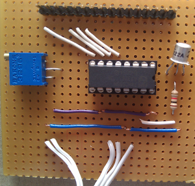
Sorry for delayed response. I'm finally back home and could take close photos of my board for anyone who wants to take a look.
My board is mounted with components facing the LCD thus I had to reverse the order of pins on the shift register. This is why I added the MSB/LSB option to the provider. In my case I use a 10K pot to adjust the contrast and backlight is turned on/off via the one remaining output of shift register.
Attached Files
-
_MG_2269.jpg 318.65KB
168 downloads
-
_MG_2273.jpg 285.68KB
153 downloads
#17
Szymon
-
- Members
-
- 108 posts
Advanced Member
- LocationPoland, Krakow
Posted 11 October 2010 - 07:09 PM
This stuff is hard to debug if you get it wrong
What I did to verify it works correctly, was simply put LEDs to each output of the shift register instead of connecting it to LCD. Then I could step through the code and observe if they are light up in correct pattern. I think the backlight would be easiest to verify. Just make a loop to turn it on/off and see if the apropriate LED will blink.
#18
Szymon
-
- Members
-
- 108 posts
Advanced Member
- LocationPoland, Krakow
Posted 11 October 2010 - 07:13 PM
Secondly the Fritzing wiring diagram on Szymon's blog page is slightly incorrect w.r.t. the SPI port:
SHCP = PIN 13 (not 12)
STCP = PIN 10
DS = PIN 11
Thanks for spoting this. In earlier version I sent data to shift register all in managed code, but later I switched to hardware SPI and thus had to move clock input pin to SPCK (pin 13).
Edit: I have updated the diagram in the blog post.
#19
Spike
-
- Members
-
- 24 posts
Member
Posted 11 October 2010 - 09:41 PM
Thanks alot for your help guys, I really appreciate it!
I am not sure how to go about measuring the pins, are you talking about physically checking their states or programmatically doing so? Sorry I am still very new to the hardware side of this!
My pins should be set up exactly to that in the diagram on Szymon's blog (as I have inspected my configuration several times!)
A few moments ago I did get some strange things appearing and being refreshed on the LCD screen. But have been unable to reproduce it.
Edit: The strange things appearing seems to be intermittent, it happened when I first turned it on this morning. Here is a picture...
Attached Files
-
IMG_3463.JPG 59.4KB
155 downloads
#20
sweetlilmre
-
- Members
-
- 62 posts
Advanced Member
Posted 13 October 2010 - 11:35 AM
Thanks alot for your help guys, I really appreciate it!
I am not sure how to go about measuring the pins, are you talking about physically checking their states or programmatically doing so? Sorry I am still very new to the hardware side of this!
My pins should be set up exactly to that in the diagram on Szymon's blog (as I have inspected my configuration several times!)
A few moments ago I did get some strange things appearing and being refreshed on the LCD screen. But have been unable to reproduce it.
Edit: The strange things appearing seems to be intermittent, it happened when I first turned it on this morning. Here is a picture...
Hi,
You may have:
- A bad ground, short etc.
- Misconfigured pin
- Inverted logic (bits in wrong order)
2. you need to check your wiring again carefully
1. same as 2.
Edit: I have tried to puzzle out your wiring by looking at your breadboard picture, but there is not enough detail. If you could textually describe your wiring (what each pin of the shift register and LCD is connected to) that would help diagnose the issue.
HTH
-(e)


0 user(s) are reading this topic
0 members, 0 guests, 0 anonymous users


