The Netduino forums have been replaced by new forums at community.wildernesslabs.co.
This site has been preserved for archival purposes only
and the ability to make new accounts or posts has been turned off.
Attached is some code to drive the HT1632 LED Matrix chip as found in the Sure Electronics DE-DP13212 and similar boards (Sure Electronics).
The code is horribly slow at the moment as a raw bit-bang approach is used to communicate with the HT1632 (and I am sure my horribly un-optimsed code does not help )
I will migrate this to SPI once variable SPI is available. At any rate here it is to look at.
This code was ported from Miles Burton's Arduino code and is released under the same GPL license.
Any pointers on optimisation would be great as C# on an embedded device is very new to me!
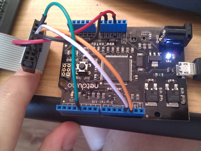
Connection is 5 wires:
Power and ground to 5V and GND pins.
ChipSelect to digital pin 4
Clock to digital pin 13
Data (WR) to digital pin 12
Hope this helps someone. I will attempt to optimise this to make it useful and to support the 2416 boards as well.
-(e)
Very cool! You've implemented "bit banged" variable-bit SPI using managed...doubly cool.
I really can't take too much of the credit, its mostly Miles Burton's code, but thanks
I think that is definitely part of the speed issue as is the memory access on the buffer arrays.
I really can't take too much of the credit, its mostly Miles Burton's code, but thanks
I think that is definitely part of the speed issue as is the memory access on the buffer arrays.
I need to have a look at that...
-(e)
Cool stuff Sweetlilmre!
I'm trying your sample with some of my 0832 boards here but I can't seem to get anything displayed on it. I have to say it are the green 0832's from SureElectronics and not the red ones don't know if that makes any difference. Just to be sure this is how I mapped the pins
I'm trying your sample with some of my 0832 boards here but I can't seem to get anything displayed on it. I have to say it are the green 0832's from SureElectronics and not the red ones don't know if that makes any difference. Just to be sure this is how I mapped the pins
Checking the 0832 Datasheet, your connections look good.
I assume you have also wired:
NetDuino GND to Matrix 11
NetDuino 5V to Matrix 12
Also that you have set the dip switches on the back of the matrix to 1=ON, 2=OFF, 3=OFF, 4=OFF?
Make sure you have the matrix connector orientation correct (I got it upside down the first time and wired 5V to GND... )
-(e)
Very strange, I did connect GND to pin 11 and 5V to 12 on the matrix, I also checked the CS selection switch and only 1 is on.. I have also some 2416 boards I tried one of those still no luck! Do you have a picture or something on how you wired yours? Or do you have any other ideas?
Very strange, I did connect GND to pin 11 and 5V to 12 on the matrix, I also checked the CS selection switch and only 1 is on.. I have also some 2416 boards I tried one of those still no luck! Do you have a picture or something on how you wired yours? Or do you have any other ideas?
Thanks!
Does this help at all?
I just rewired it and tested it out. It all seems to work OK?
On the ribbon side, the pins are:
The 2416 will not work as the addressing mode is different. (well it might display something, but certainly not what is intended, I must get one of those to play with though...)
The 2416 will not work as the addressing mode is different. (well it might display something, but certainly not what is intended, I must get one of those to play with though...)
HTH
-(e)
Thanks for the picture! My configuration is exactly the same! So it can't be the wiring, you said the 2416 won't work because of a different pixel mapping.. I have read somewhere that the pixel mapping of the green 0832 is different from the red 0832 too just like the green 2416 pixel mapping is different from the red one.
The code runs just fine I have checked if the matrices are getting power. I really have no idea what is going wrong.
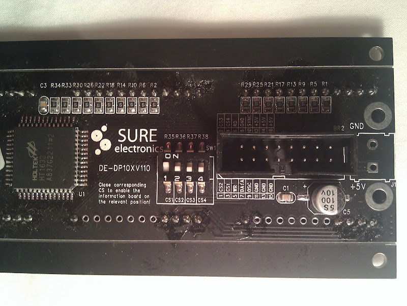
This is what is on the back of my 0832:
Is that the same as yours?
Thanks again for your help! I really hope I can get it to work!
Thanks for the picture! My configuration is exactly the same! So it can't be the wiring, you said the 2416 won't work because of a different pixel mapping.. I have read somewhere that the pixel mapping of the green 0832 is different from the red 0832 too just like the green 2416 pixel mapping is different from the red one.
The code runs just fine I have checked if the matrices are getting power. I really have no idea what is going wrong.
This is what is on the back of my 0832:
Is that the same as yours?
Thanks again for your help! I really hope I can get it to work!
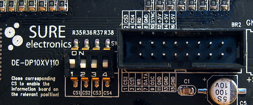
I can't imagine the mapping is different if they are using the same display driver... I have the Yellow one btw.
Here is a close up (sorry about the washed out look, but the lighting in my study is terrible at night)
The only other thing I can suggest is that you have a bad connection. My clock line was dodgy initially and nothing would display.
Well I'm going to give up for now I tried everything, I cut a connector from one of the cables and soldered the pins directly to it but I can't seem to get anything out of it.
I have 8 matrices and tried them all no luck with all of them. I really do not hope it is my netduino that is faulty or something.
I'm going to order a red 0832 matrix from sure to see if that one works for me..
One other thing I have thought of.. did you change anything in your firmware? maybe I have an older firmware or something? or isn't that possible, i'm such a newbee with Netduino
Hi,
Damn this is frustrating!
I run custom firmware for the bitbanger mod I made but this should not be a issue (the code attached is the original code I developed on stock firmware).
Do you by any chance have an Arduino? If so try the code from Miles Burton (linked in the first post) with your matrix and see if that works.
As a last option I reflashed with the original firmware to make sure there were no funnies there: 4.1.0.3 firmware
Then rebuilt the attached code and deployed it, it runs as expected. Try and do the firmware update, just in case. I have a watch on this topic so post back when you get the red matrix. I'd love to see this resolved!
Now to reflash back to custom...
-(e)
Hmm that was a good suggestion to try it on my Arduino.. you can see the result below:
http://www.youtube.com/watch?v=Lmn4nZ0OKyE
I have downloaded the latest code from Miles Burton his site and as you can see it runs perfectly! strange stuff he!
Whoot Whoot! Solved it! I tried the link you provided with the 4.1.0.3 firmware flashed the firmware and after the upgrade was finished I instantly saw something displayed on my Matrix!!
So the solution was flashing the updated firmware, now I have the same result as in the video posted earlier but the with my Netduino!
Thanks a million for helping me out! I will now try to make some extra functionality to run more than one display for example.. or do you have more recent code?
YAYAYAYAY!! Awesome!
I have some more recent code that uses the custom bitbanger firmware to really blast the display (it so much faster its unbelievable).
I need to fix it up so that compilation is conditional i.e. you don't need special firmware, and I have optimised the font drawing and some other bits.
I'll take a look tonight and see if I can post it up.
-(e)
Wow that would be awsome! I have 4 displays connected now and as you said it is very slow, the text crawls across the displays I really hope you can post your code tonight. My ultimate goal is to get the displays working in combination with a Ethernet Shield so you can send messages to the Netduino and displays it on the matrices.
One other thing, do you think it is possible to connect more then 4 displays? lets say for example 8?
I implemented my own version of the HT1632 interface using variable-length SPI on the Netduino using the latest alpha firmware. It was really tricky because the HT1632 interface is just spi-like, not 100% (it varies the word length, and expects CS to be active to do bulk write). I had to do bit-operations in the memory buffer to get it to work. It currently only supports the green 2614 from Sure Electronics (as it's the only one I have access to).
The output to the displays is wicked fast (about 1 ms to do a full frame output), but the bit-access to the memory array isn't that fast. I wish we could modify the spi word length on the fly, and keep CS active between writes... WISH
The output to the displays is wicked fast (about 1 ms to do a full frame output), but the bit-access to the memory array isn't that fast. I wish we could modify the spi word length on the fly, and keep CS active between writes... WISH
Hauk,
Can you explain your wish in more detail? Not sure how much we can do here without shaking up the .NET MF architecture, but I'd like to look into it...
Can you explain your wish in more detail? Not sure how much we can do here without shaking up the .NET MF architecture, but I'd like to look into it...
I have hit the same issues: it is not possible to change configuration of SPI (and SerialPort etc.) because properties are read-only, so a new instance must be created with the new configuration values passed via constructor, which causes side effects like extra pulses due to initialization code - pins are being reserved, set-up etc. Additionally, every call to SPI write method always initializes (see Xaction_Start(...)) and then uninitializes (Xaction_Stop(...)) signal pins - this means it is not possible to have subsequent calls without extra transitions on clock and chip select lines. I hope in the next version such code will be moved from write method (e.g. to constructor), so it is performed only once. Alternatively, support of Chip Select Active After Transfer (CSAAT) would help too...
Can you explain your wish in more detail? Not sure how much we can do here without shaking up the .NET MF architecture, but I'd like to look into it...
Chris
I have three wishes, not sure how they would be implemented, I don't know much about the MF arch, but here they are:
Change the SPI word length on the fly, ie before each transfer. The HT1632-based displays need 14 bits for one data transfer, 15 for commands, and 14+8,8,8,etc for bulk transfer.
Hold CS/latch high between transfers. If I could do that then I think I could set the SPI word length to 14 bits, send the data transfer command and then bulk load with spi.Write(byte) to send out 8-bits for the bulk. But the bulk load gets interrupted when CS goes inactive in the HT1632 controller.
Change the CS pin for SPI on the fly (I need one pin per display module). Now I have to dispose/create an SPI instance before each transfer to each display (I have 4).


 )
) LedMatrix.zip 14.17KB
77 downloads
LedMatrix.zip 14.17KB
77 downloads


 I really hope you can post your code tonight. My ultimate goal is to get the displays working in combination with a Ethernet Shield so you can send messages to the Netduino and displays it on the matrices.


