

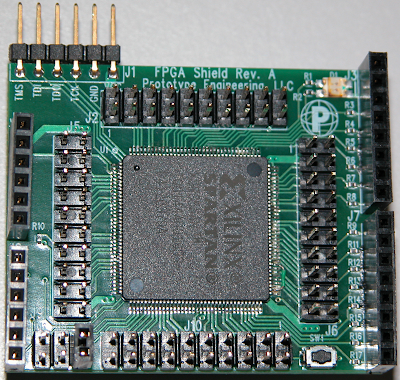
Top:
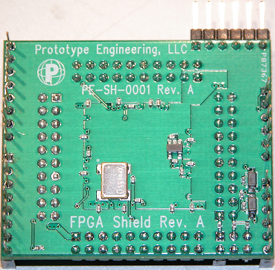
Bottom:
Xilinx XC3S50AN 50,000 gate FPGA
64 IO available on 4 dedicated headers
16 IO available to Netduino (D0-D13, TWD, TWCK)
50 MHz clock oscillator
red/green bicolor LED
momentary pushbutton
JTAG pads available for advanced development (the six-pin right angle header at the top left corner, which would typically not be populated)
Some common questions:
What's an FPGA?
An FPGA is a Field Programmable Gate Array. Think of it as a huge array of logic gates (50,000 in this case), which you can configure to suit your needs. In addition, there are clock generators, dedicated multipliers, RAM, flash, and many other useful digital blocks. The logic is an order of magnitude faster than anything that might commonly be found on a breadboard, and it can be easily reconfigured when you move on to a different project.
What can I do with it?
All sorts of stuff. There are plenty of resources on board for applications ranging from basic glue logic to port expansion (essentially 64 more GPIOs) to PWM to motor control. More advanced applications might include high speed digital signal processing, buffered wireless communications, bus capture and digital waveform analysis.
How do I configure it?
Xilinx has made freely available a toolchain for their smaller FPGAs which they call Webpack. The logic structure can be described either using a Hardware Description Language (Verilog, VHDL) or by using schematic capture, basically drawing your gate arrangement in schematic form. Once the design is complete, a bitstream is generated and downloaded into the nonvolatile memory (flash) on the FPGA.
How is the bitstream loaded?
After the bitstream is generated on the PC, it's processed into a handful of resource files which are then deployed to the Netduino along with a script to program the bitstream into the flash on the FPGA. Once the bitstream is programmed, the FPGA will load that bitstream on every subsequent boot. No further intervention is necessary by either the user or the Netduino. For Netduino Plus users, the bitstream can also be written to a microSD on the PC, then transferred to the Netduino. Once on the Netduino, a script is run to transfer the bitstream from the microSD to the FPGA's flash. The microSD approach is the only option available to Netduino Plus users with the standard (48K) firmware.
Why is this even necessary?
The Netduino is a tremendously capable platform, and it's very well suited to many uses. There are two areas where the FPGA shield is able to supplement the Netduino, however: IO and real-time processing. The FPGA shield can provide an additional 64 IO, and depending on configuration, can do this while making all 14 digital IO pins on the Netduino available. As for real-time processing, some tasks like high-speed motor control, IR remote encoding/decoding, video, and sensitive asynchronous serial communications are beyond the abilities of the C# environment of the Netduino. They're either too timing-sensitive or too processor intensive to be feasible. These tasks could be offloaded to the FPGA, while the Netduino manages state and communications.
How/when can I get one?
If you're interested in being one of the alpha testers, please drop me an email at ward@prototype-eng.com and we'll talk. General availability will depend on the community's response, how the alpha test goes, and whether it looks like a beta's necessary. Within the next 2-3 months is not unreasonable if testing goes well and there's a healthy demand.
So fire away with questions, comments, and criticism...I look forward to hearing what people think. Thanks!
--Ward


